
Indoor unit of air conditioner and air conditioner

An air-conditioning indoor unit and air-conditioning technology, applied in air-conditioning systems, space heating and ventilation, heating methods, etc., can solve the problems of air supply angle and height restrictions, small air supply surface, and small air supply height of air-conditioning indoor units, etc. Achieve the effect of expanding the air supply width, avoiding dust entry, and increasing the air supply height

Active Publication Date: 2015-01-14
HAIER GRP CORP +1
View PDF9 Cites 0 Cited by
  • Summary
  • Abstract
  • Description
  • Claims
  • Application Information

AI Technical Summary

Problems solved by technology

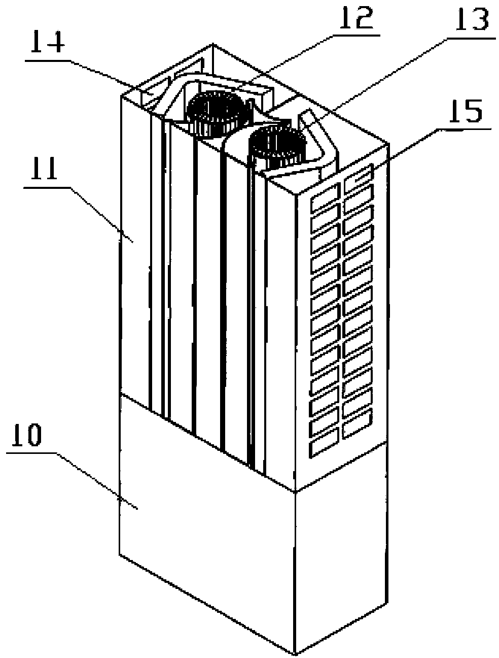
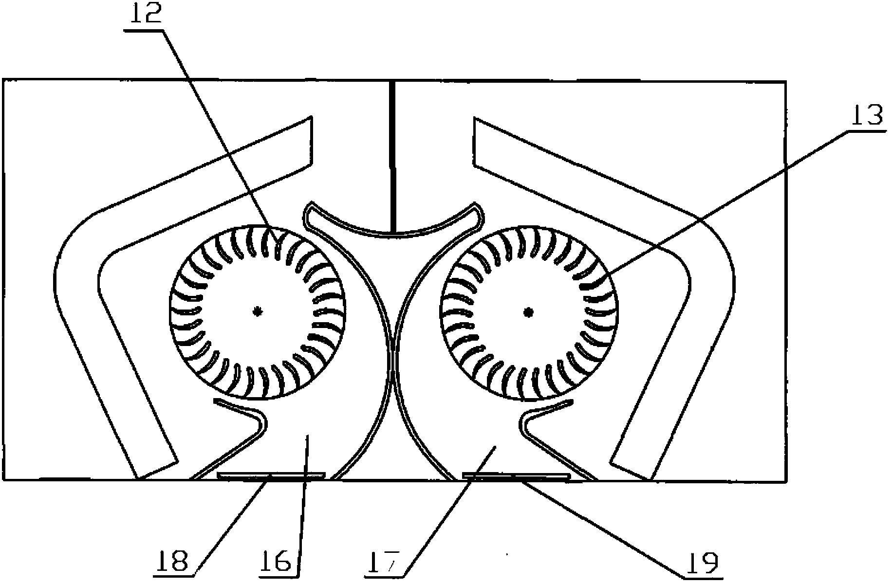
[0007] Depend on figure 1 and figure 2 It can be seen that the above-mentioned upper frame 11 has a symmetrical structure, and the distance between the left air outlet 16 and the right air outlet 17 is relatively small, and the air is supplied to the left and right sides respectively, which results in that the horizontal width of the air supply is not large enough, and the air supply On the other hand, in the upper frame 11, a left cross-flow fan 12 and a right cross-flow fan 13 are vertically arranged on the left and right sides respectively, and the height of the current cross-flow fans is relatively Smaller, and subject to various restrictions, so the air supply height of the above-mentioned existing air-conditioning indoor units in the vertical direction is relatively small
In summary, the air supply angle and height of the above-mentioned existing air-conditioning indoor units are limited

Method used


Image

  • Indoor unit of air conditioner and air conditioner
  • Indoor unit of air conditioner and air conditioner
  • Indoor unit of air conditioner and air conditioner

Examples


Embodiment Construction

[0035] In order to enable those skilled in the art to better understand the technical solutions of the present invention, the present invention will be further described in detail below in conjunction with the accompanying drawings and specific embodiments.

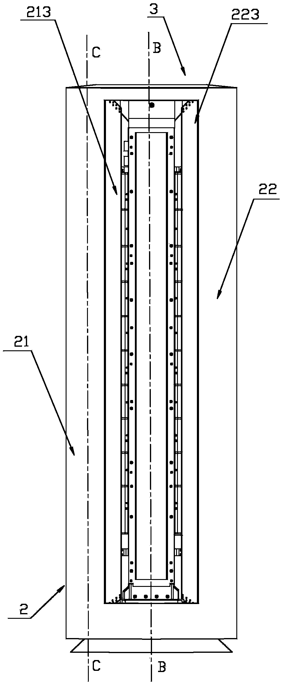
[0036] Please refer to Figure 3-6 , image 3 It is a schematic diagram of the front structure of the air conditioner indoor unit provided by the present invention in a specific embodiment; Figure 4 for image 3 The cross-sectional structural schematic diagram of the air-conditioning indoor unit along the B-B direction in ; Figure 5 for image 3 The cross-sectional structural diagram of the air-conditioning indoor unit along the C-C direction in ; Image 6 for Figure 5 The cross-sectional structural diagram of the air-conditioning indoor unit along the direction A-A in .

[0037] The air-conditioning indoor unit 3 of the present invention has a frame structure 2, and the frame structure 2 includes a left column 2...


PUM


Abstract

The invention provides an indoor unit of an air conditioner and the air conditioner. The indoor unit of the air conditioner is large in air supply width and air supply height. The indoor unit of the air conditioner is of a frame structure. The frame structure comprises a left stand column and a right stand column, wherein the left stand column and the right stand column are each in a cavity shape. The cavity of the left stand column and the cavity of the right stand column are each provided with at least one cross-flow fan which penetrates through the corresponding cavity vertically. According to the indoor unit of the air conditioner, the indoor unit is of the frame structure, the left side and the right side of the frame structure are provided with the left stand column and the right stand column respectively, the cross-flow fans are arranged in the two stand columns in a vertically penetrating mode, the cross-flow fans arranged in the vertically penetrating mode can achieve air supply at two heights in the vertical direction, and therefore the air supply height can be effectively increased.

Description

technical field [0001] The invention relates to the technical field of air conditioners, in particular to an air conditioner indoor unit. The present invention also relates to an air conditioner provided with the above air conditioner indoor unit. Background technique [0002] The air conditioner indoor unit is a heat exchanger installed indoors, and is an important part of the current split air conditioner. Usually, the existing air conditioner indoor unit has a vertical structure, and the whole body of the air conditioner is arranged vertically, which is also called a floor-standing air conditioner indoor unit. [0003] Please refer to figure 1 with figure 2 , figure 1 It is a three-dimensional structural schematic diagram of a setting method of an air-conditioning indoor unit in the prior art; figure 2 for figure 1 The schematic diagram of the cross-sectional structure of the indoor unit of the air conditioner shown. [0004] The patent No. CN101957020A discloses...

Claims


Application Information

Patent Timeline
Patent Type & Authority Applications(China)
IPC IPC(8): F24F1/00F24F13/10
CPCF24F1/0003F24F13/10
Inventor 杜鹃吴剑周枢费兆军
Owner HAIER GRP CORP
Learn More