
Touch screen and display panel

A display panel and touch screen technology, which is applied in the direction of instruments, calculations, electrical digital data processing, etc., can solve the problems of easy aging of application characteristics, insufficient precision, low light transmittance, etc., and achieve visual and tactile enjoyment and touch response Sensitive, reduce screen power consumption effect

Inactive Publication Date: 2015-01-14
HEFEI XINSHENG OPTOELECTRONICS TECH CO LTD +1
View PDF5 Cites 27 Cited by
  • Summary
  • Abstract
  • Description
  • Claims
  • Application Information

AI Technical Summary

Problems solved by technology

Among them, the resistive touch screen is simple in design and low in cost, but the resistive touch screen touch is more restricted by its physical limitations, such as low light transmittance, and the large detection area with high line count causes processor burden, and its application characteristics make it Easy to age and affect service life
The capacitive touch screen supports multi-touch function, has higher light transmittance, lower overall power consumption, its contact surface has high hardness, no need to press, and has a long service life, but the accuracy is insufficient, and it needs a conductor or a capacitive pen to control

Method used


Image

  • Touch screen and display panel
  • Touch screen and display panel
  • Touch screen and display panel

Examples


Embodiment 1

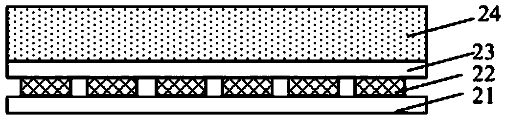
[0030] This embodiment provides a touch screen, such as figure 1 As shown, the touch screen 2 includes a first electrode 21, a second electrode 23, and a sensing layer 22 located between the first electrode 21 and the second electrode 23. The sensing layer 22 is formed of a transparent material with a piezoelectric effect.

[0031] Among them, the so-called piezoelectric effect refers to: when some dielectrics are deformed (including bending deformation and stretching deformation) by external forces in a certain direction, polarization will occur inside them, and at the same time, on its two opposite surfaces Positive and negative electrical signals appear on the When the external force is removed, it will return to the uncharged state. This phenomenon is called the positive piezoelectric effect. When the direction of the applied force changes, the polarity of the electrical signal also changes. The sensing layer 22 in the touch screen of this embodiment is a piezoelectric s...

Embodiment 2

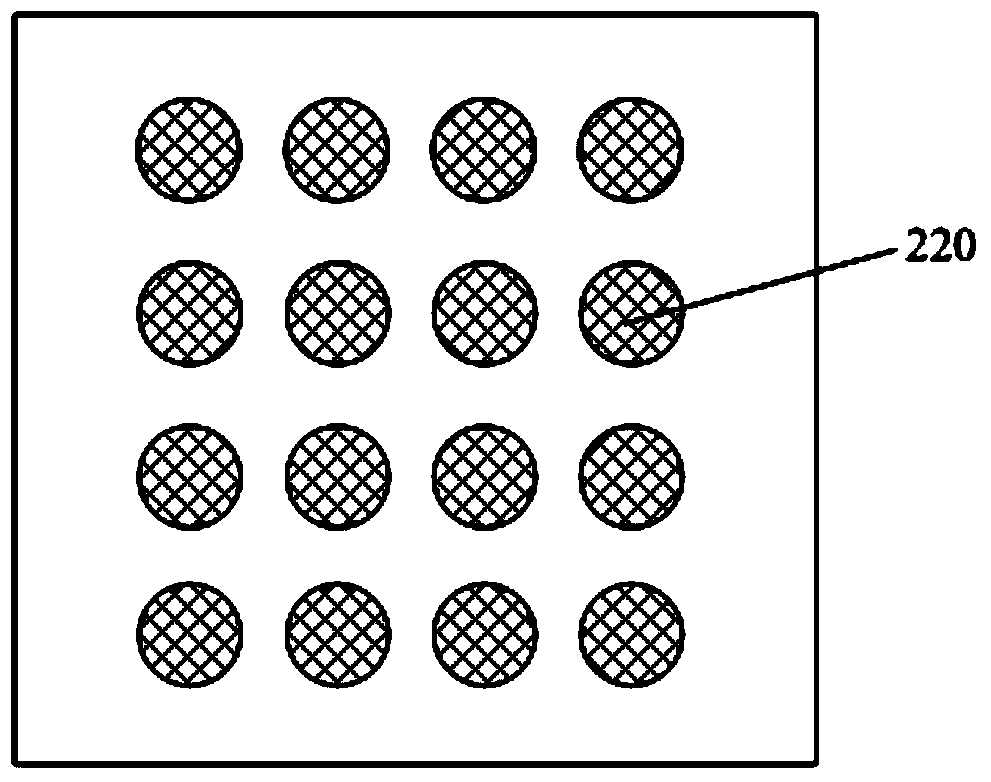
[0048] This embodiment provides a touch screen. Compared with Embodiment 1, the shape or arrangement of the sensing layer 22 in the touch screen is different.

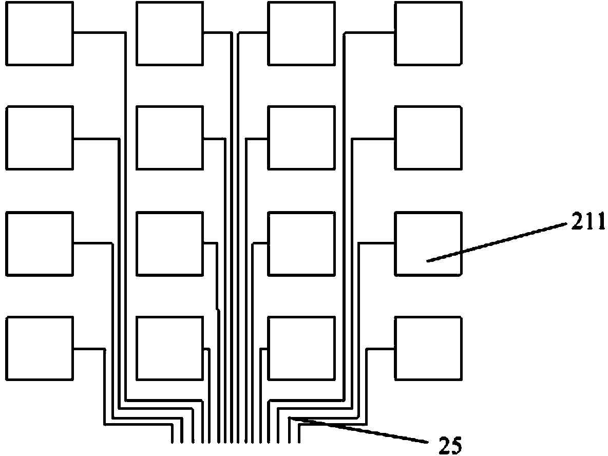
[0049] Specifically, such as Figures 3A-3C As shown, the sensing layer 22 includes a grid-shaped piezoelectric sensing module 220 formed by fusion of a plurality of vertically intersecting strip sensors, the first electrode 21 includes a plurality of first strip electrodes 212, and the second electrode 23 includes a plurality of strip sensors. A second strip-shaped electrode 232, the first strip-shaped electrode 212 and the second strip-shaped electrode 232 are vertically intersected, and are respectively arranged corresponding to the strip-shaped sensors with the same arrangement direction, and each first strip-shaped electrode 212 is connected to the second strip-shaped electrode 232. The strip electrodes 232 are connected to the processor through the transmission line 25 . in, Figure 3A The intersecting area of ...

Embodiment 3

[0052] This embodiment provides a display panel, which includes the touch screen in Embodiment 1 or Embodiment 2.

[0053] Such as Figure 4 As shown, the display panel includes a display screen 1 and a touch screen 2 arranged outside the display screen 1 . In the manufacturing process of the display panel, the display screen 1 and the touch screen 2 are bonded together to form a whole.

[0054] In this embodiment, preferably, the display screen 1 is a liquid crystal display screen, an OLED display screen or a plasma display screen. Using the touch screen in Embodiment 1 or Embodiment 2, it can be laminated with different types of display screens to form a touch display module, display panel or display device, which is very simple and practical.

[0055] The display panel can be any product or component with a display function such as a liquid crystal panel, an electronic paper, an OLED panel, a mobile phone, a tablet computer, a television set, a monitor, a notebook compute...


PUM


Abstract

The invention belongs to the technical field of displays, and particularly relates to a touch screen and a display panel. The touch screen comprises a first electrode, a second electrode and an induction layer positioned between the first electrode and the second electrode, wherein the first electrode and the second electrode are oppositely arranged, the induction layer is made of a transparent material with a piezoelectric effect. The touch screen is capable of directly converting a pressure of a touch object into an electric signal so that a position of a to-be-touched point can be induced and the induction can be made for the size of an acting force and a change characteristic, and has the advantages of being sensitive in touch response and supporting multi-point touch, and the like, thereby being capable of inducing the pressure of any object, and reducing the power consumption greatly, and being capable of effectively reducing the power consumption of a screen. Correspondingly, the touch operation of the display panel adopting the touch screen is not limited by insulation of the to-be-touched object, the power consumption is less, and the enjoyment of vision and touch of people is relatively met.

Description

technical field [0001] The invention belongs to the field of display technology, and in particular relates to a touch screen and a display panel. Background technique [0002] Currently, the most widely used touch screens include resistive touch screens and capacitive touch screens. Among them, the resistive touch screen is simple in design and low in cost, but the resistive touch screen touch is more restricted by its physical limitations, such as low light transmittance, and the large detection area with high line count causes processor burden, and its application characteristics make it It is easy to age and thus affects the service life. The capacitive touch screen supports multi-touch function, has higher light transmittance, lower overall power consumption, its contact surface has high hardness, no need to press, and has a long service life, but the accuracy is insufficient, and it needs a conductor or a capacitive pen to manipulation. [0003] Designing a touch scr...

Claims


Application Information

Patent Timeline
Patent Type & Authority Applications(China)
IPC IPC(8): G06F3/041
CPCG06F3/0414G06F2203/04104G06F3/0416G06F2203/04103G06F3/04144G06F1/3262G06F3/0412G06F3/045G06F2203/04105
Inventor 王庆浦胡明
Owner HEFEI XINSHENG OPTOELECTRONICS TECH CO LTD
Learn More