
Photoelectric switching device and electrical switchgear equipped with the photoelectric switching device

A technology of electrical switch and photoelectric conversion, which is applied in the direction of coupling device, optical waveguide coupling, circuit, etc., and can solve problems such as wiring errors and long outage time

Active Publication Date: 2016-08-17
GUANGZHOU POWER SUPPLY BUREAU GUANGDONG POWER GRID CO LTD
View PDF4 Cites 0 Cited by
  • Summary
  • Abstract
  • Description
  • Claims
  • Application Information

AI Technical Summary

Problems solved by technology

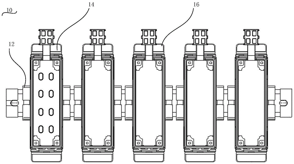
[0004] Based on this, it is necessary to provide a photoelectric transfer that does not change the original terminal connection mode in the relay protection device and the switch cabinet to achieve fast transfer in order to solve the problems of long outage time and easy wiring errors caused by the transformation of the relay protection device. device and an electrical switchgear equipped with the photoelectric switching device

Method used


Image

  • Photoelectric switching device and electrical switchgear equipped with the photoelectric switching device
  • Photoelectric switching device and electrical switchgear equipped with the photoelectric switching device
  • Photoelectric switching device and electrical switchgear equipped with the photoelectric switching device

Examples


Embodiment Construction

[0027] In order to facilitate the understanding of the present invention, the present invention will be described more fully below with reference to the associated drawings. Preferred embodiments of the invention are shown in the accompanying drawings. However, the present invention can be embodied in many different forms and is not limited to the embodiments described herein. On the contrary, these embodiments are provided to make the understanding of the disclosure of the present invention more thorough and comprehensive.

[0028] It should be noted that when an element is said to be "fixed" to another element, it may be directly on the other element or there may be an element in between. When an element is referred to as being "connected to" another element, it can be directly connected to the other element or there may be both elements in between.

[0029] Unless otherwise defined, all technical and scientific terms used herein have the same meaning as commonly understoo...


PUM


Abstract

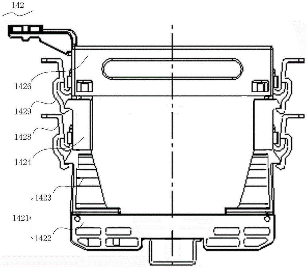
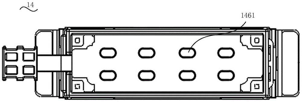
The invention discloses a photoelectric switching device and an electrical switch cabinet provided with the photoelectric switching device. The photoelectric switching device comprises a mounting base and switching mechanisms, wherein each switching mechanism comprises a mold frame and a switching component installed on the corresponding mold frame, each mold frame comprises a bottom base, middle connecting clamps and a top mold frame body, each bottom base is installed on the mounting base, one end of each connecting clamp is detachably connected to the corresponding bottom base, the other end of each connecting clamp is detachably connected to the corresponding top mold frame body, and the switching components are installed on the top mold frame bodies and / or the connecting clamps; each switching component is an optical switching adapter assembly or an electrical switching insertion core body. The photoelectric switching device is located in the electrical switch cabinet. According to the photoelectric switching device, an optical switching mechanism is clamped and fastened to the mounting base, and optical fiber switching can be rapidly achieved through the optical switching adapter assembly arranged on the first top mold frame body; an electrical switching mechanism is clamped and fastened to the mounting base, and electrical switching can be rapidly achieved through the electrical switching insertion core body.

Description

technical field [0001] The invention relates to the technical field of electrical equipment, in particular to a photoelectric switching device and an electrical switch cabinet provided with the photoelectric switching device. Background technique [0002] The secondary devices of the switch bays of 10KV and 35KV substations are basically installed on-site, that is, the secondary devices are installed on the switch cabinet door, and the secondary wiring on the back panel of the secondary device is directly connected to the terminal block in the switch cabinet. Affected by the life of electronic components, the normal service life of intelligent relay protection devices is about ten years. The service life of primary substation equipment is usually 25-30 years, so the intelligent relay protection device needs to be updated once or twice during the life cycle of the primary equipment. [0003] Traditionally, when the relay protection device is modified, it is necessary to re-c...

Claims


Application Information

Patent Timeline
Patent Type & Authority Patents(China)
IPC IPC(8): H01R31/06G02B6/42
CPCG02B6/42H01R31/065
Inventor 徐强超陈宇强江文东叶石丰邱新娟
Owner GUANGZHOU POWER SUPPLY BUREAU GUANGDONG POWER GRID CO LTD
Learn More