Tenoning assist mechanism

An auxiliary mechanism and tenoning technology, which is applied in the direction of mortising machines, slotting machines, wood processing equipment, etc., can solve the problems of insufficient tenoning stability and scattered pressing force, so as to achieve a compact overall structure and provide The effect of tenoning precision

Inactive Publication Date: 2015-01-21
杨绍波
View PDF11 Cites 6 Cited by
  • Summary
  • Abstract
  • Description
  • Claims
  • Application Information

AI Technical Summary

Problems solved by technology

However, the pressing force provided by the two pressing plat...

Method used


Image

  • Tenoning assist mechanism
  • Tenoning assist mechanism

Examples


Embodiment Construction

[0029] The present invention will be described in further detail below in conjunction with the accompanying drawings.

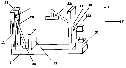
[0030] like figure 1 , the tenoning auxiliary mechanism includes a U-shaped workbench frame 1 , a first mechanism 2 , and a second mechanism 3 . The first mechanism 2 and the second mechanism 3 are respectively arranged on the two longitudinal sides of the U-shaped workbench frame 1, wherein the first mechanism 2 includes a first cylinder 21, a movable part 22, a push bar 23, a push block 24. The second mechanism 3 includes a second cylinder 31 and a rotating rod 32 , and the two ends of the rotating rod 32 respectively have a clamping plate 321 and an action plate 322 .

[0031] A first mechanism is arranged on a longitudinal side of the U-shaped workbench frame 1, and the first cylinder 21 faces the movable part 22, and an annular ring can be arranged at the end of the first cylinder 21, that is, the end of its contact surface with the movable part 22. co...


PUM


Abstract

The invention belongs to the technical field of wood processing and relates to a tenoning assist mechanism comprising a U-shaped bench rack, a first mechanism and a second mechanism. The U-shaped bench rack providing a workpiece with side clamping force is used for supporting the workpiece. The first mechanism is used for providing side clamping power. The second mechanism is used for providing top clamping power. The first mechanism and the second mechanism are arranged on two vertical sides of the U-shaped bench rack. The first mechanism and the second mechanism providing the side clamping force and top clamping force respectively are applied to replace existing simple clamping structures, the whole structure is compact, the center of gravity of the tenoning assist mechanism is lowered, the first mechanism, the second mechanism and the U-shaped mechanism co-act to provide the top compressing force, side compressing force and corner force to clamp the workpiece, and tenoning precision is improved.

Description

technical field [0001] The invention relates to the technical field of wood processing, in particular to a tenoning auxiliary mechanism. Background technique [0002] In the past, tenoning on wooden boards was done manually, using chisels and iron saws. The disadvantages were low efficiency and inaccurate processing dimensions. At present, in the process of processing the tenon, it is generally processed by a tenoning machine. The existing tenoning machine, such as the utility model patent ZL95216554.6, generally uses a cylinder to control two pressing plates to act on the tenoning work piece, and one is used as the upper pressing plate. It provides the upper pressing force, and the other one serves as the side pressing plate to provide the side pressing force, so as to realize the firm clamping of the tenoning work piece, thereby improving the precision of subsequent tenoning. However, the pressing forces provided by the two pressing plates are relatively scattered, an...

Claims


Application Information

Patent Timeline
IPC IPC(8): B27F5/02
CPCB27F5/02
Inventor 姚仲民
Owner 杨绍波
Why Eureka
Try Eureka