Airflow rotary table spinning device used for preparing nanofiber
A spinning device and nanofiber technology, which is applied in the field of air-rotating spinning devices, can solve the problems of far from meeting the requirements of industrialization, high price, and inability to use industrialized production, and can solve the problems of low output of electrospinning and difficulty in nanometer production. to overcome the effects of difficult nano-ization
- Summary
- Abstract
- Description
- Claims
- Application Information
AI Technical Summary
Problems solved by technology
Method used
Image
Examples
Embodiment 1
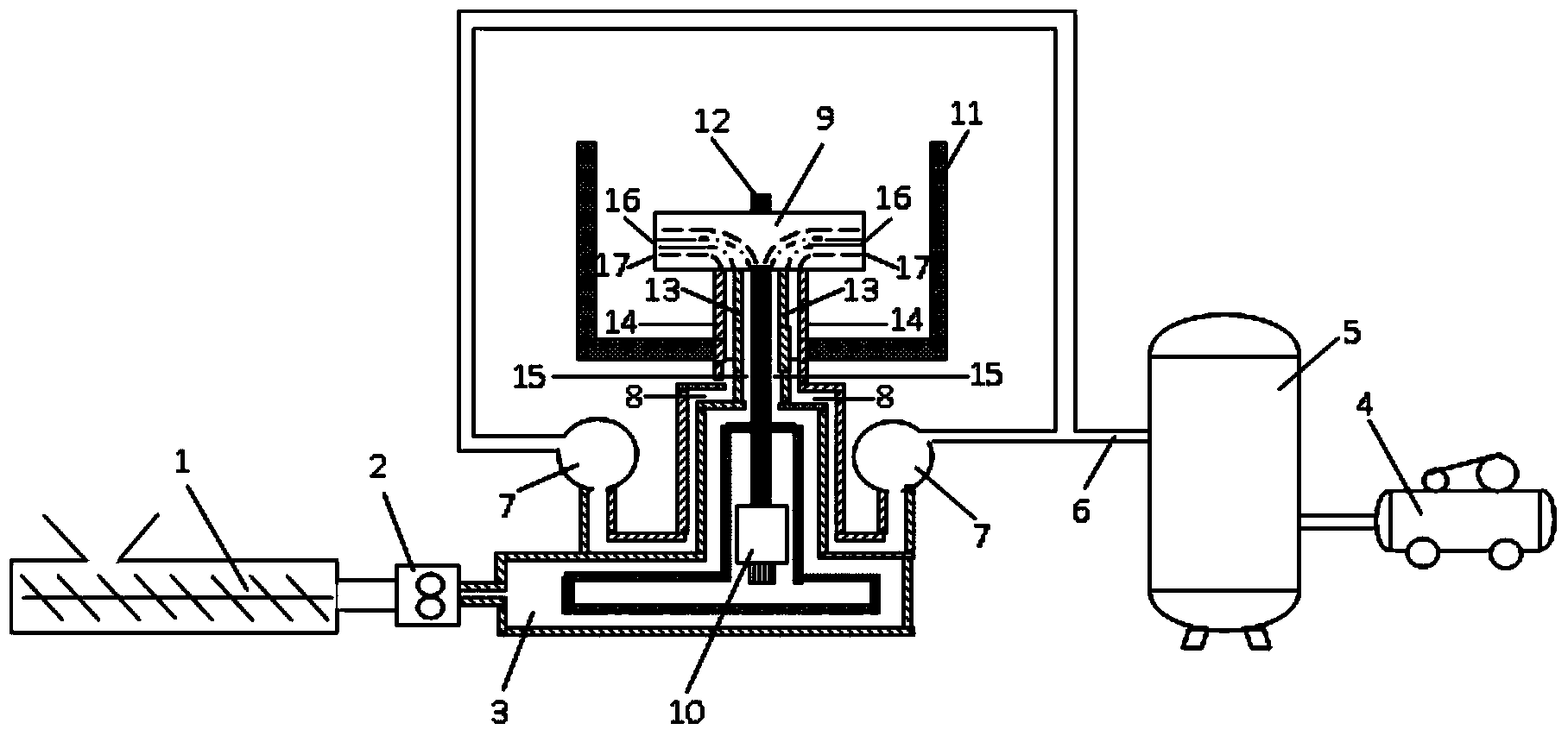
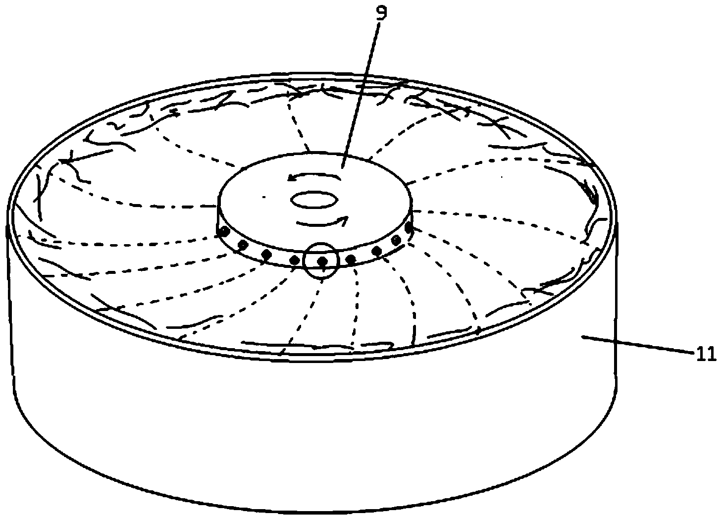
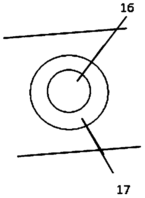
[0030] The spinning melt comes out of the screw extruder or the spinning solution supplier 1, and enters the spinning melt or solution channel 15 through the metering pump 2 and the spinning melt or solution distribution channel 3; the gas comes out from the air compressor 4 , enter the gas manifold 7 through the gas storage tank 5 and the gas supply pipeline 6; the spinneret 9 rotates at a high speed under the drive of the motor 10, and the spinning melt or solution flows from the spinneret hole under the action of the inertial force generated by the high-speed rotation 16 is thrown out to form a filament; the high-speed gas is ejected from the annular airflow nozzle 17 through the airflow channel 8; the filament is rapidly stretched and thinned into nanofibers under the combined action of inertial force and airflow force, and forms a fiber product on the collector 11 . Among them, the spinneret hole 16 has a diameter of 0.4mm, the inner and outer diameters of the annular air...
Embodiment 2
[0033] The spinning solution comes out from the screw extruder or the spinning solution supplier 1, and enters the spinning melt or solution channel 15 through the metering pump 2 and the spinning melt or solution distribution channel 3; the gas comes out from the air compressor 4, Enter the gas manifold 7 through the gas storage tank 5 and the gas supply pipeline 6; the spinning turntable 9 rotates at a high speed driven by the motor 10, and the spinning melt or solution flows from the spinning hole 16 under the action of the inertial force generated by the high-speed rotation. The high-speed gas is ejected from the annular airflow nozzle 17 through the airflow channel 8; the silkline is rapidly stretched and thinned into nanofibers under the combined action of inertial force and airflow force, and forms a fiber product on the collector 11. Among them, the spinneret hole 16 has a diameter of 0.4mm, the inner and outer diameters of the annular airflow nozzle 17 are 0.4mm and 2....
Embodiment 3
[0036] The spinning solution comes out from the screw extruder or the spinning solution supplier 1, and enters the spinning melt or solution channel 15 through the metering pump 2 and the spinning melt or solution distribution channel 3; the gas comes out from the air compressor 4, Enter the gas manifold 7 through the gas storage tank 5 and the gas supply pipeline 6; the spinning turntable 9 rotates at a high speed driven by the motor 10, and the spinning melt or solution flows from the spinning hole 16 under the action of the inertial force generated by the high-speed rotation. The high-speed gas is ejected from the annular airflow nozzle 17 through the airflow channel 8; the silkline is rapidly stretched and thinned into nanofibers under the combined action of inertial force and airflow force, and forms a fiber product on the collector 11. Among them, the diameter of spinneret hole 16 is 0.3mm, the inner diameter and outer diameter of annular airflow nozzle 17 are 0.3mm and 2...
PUM
| Property | Measurement | Unit |
|---|---|---|
| diameter | aaaaa | aaaaa |
| melt flow index | aaaaa | aaaaa |
Abstract
Description
Claims
Application Information
 - R&D
- Intellectual Property
- Life Sciences
- Materials
- Tech Scout
- Unparalleled Data Quality
- Higher Quality Content
- 60% Fewer Hallucinations
Browse by: Latest US Patents, China's latest patents, Technical Efficacy Thesaurus, Application Domain, Technology Topic, Popular Technical Reports.
© 2025 PatSnap. All rights reserved.Legal|Privacy policy|Modern Slavery Act Transparency Statement|Sitemap|About US| Contact US: help@patsnap.com


