Ring spinning machine with sensor for detecting movement of traveller

A technology of ring spinning machine and traveler, which is applied in the direction of continuous winding spinning machine, spinning machine, textile and paper making, etc. It can solve the problems such as the limitation of the accessibility of the spinning ring and achieve increased convenience Effect

Active Publication Date: 2015-01-21
SAURER GERMANY GMBH & CO KG
View PDF7 Cites 2 Cited by
  • Summary
  • Abstract
  • Description
  • Claims
  • Application Information

AI Technical Summary

Problems solved by technology

The accessibility of the spinning rings is at least limited

Method used


Image

  • Ring spinning machine with sensor for detecting movement of traveller
  • Ring spinning machine with sensor for detecting movement of traveller

Examples


Embodiment Construction

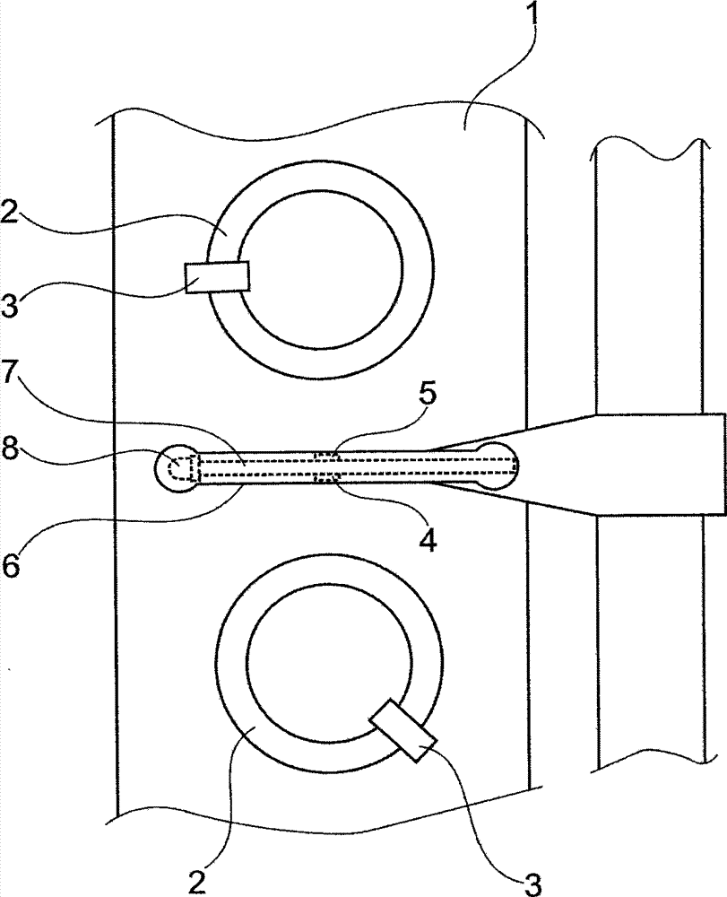
[0020] figure 1 A plan view of a ring bar 1 of a ring spinning machine is shown. The ring bar 1 has a spinning ring 2 on which a traveler 3 is mounted rotatably in each case. The spacer 6 is arranged above the ring bar 1 . A spacer 6 is arranged between two spinning rings 2 or between two spinning positions of a ring spinning machine in order to limit the formation of thread balloons during ring spinning and to avoid adjacent The contact of the thread balloon at the spinning position. During the spinning operation, the spacer 6 moves up and down together with the ring bar 1 .

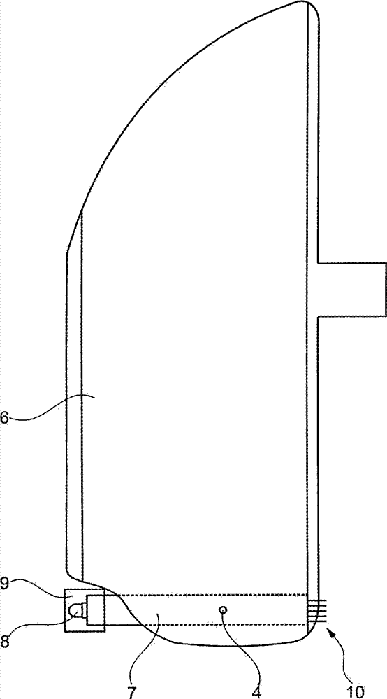
[0021] like figure 1 and 2 As shown, the spacer 6 has a printed circuit board 7 . figure 2 The spacer is shown in side view. A printed circuit board 7 is arranged in the lower region of the spacer 6 . In other words, the printed circuit board 7 is located at the end of the spacer 6 facing the ring bar 1 . This arrangement in the lower region of the spacer 6 is due to the required tightness rel...


PUM


Abstract

The invention relates to a ring spinning machine with a sensor for detecting movement of a traveller. The ring spinning machine has a ring rail (1), spinning rings (2) arranged on the ring rail (1) and travelers (3) rotatably mounted on the spinning rings (2) in any condition. The ring spinning machine has sensors (4,5) for detecting the movement of the travelers (3). A separator (6) is arranged between two adjacent spinning rings (2) above the ring rail (1) so that the distance from the seperator (6) to the ring rail (1) is kept constant when the ring rail (1) is lifted. According to the invention, the sensors are configured as loudspeakers (4, 5) and are arranged at a lower region of the seperator (6) and are held by the seperator (6). The invention also relates to the separator (6).

Description

technical field [0001] The invention relates to a ring spinning machine with a ring bar, a spinning ring on which, in each case, a traveler is mounted in a sliding manner and arranged on the ring bar. Sensors are used to detect the movement of the traveler. The spacer is arranged above the ring bar between two adjacent spinning rings so that the distance from the ring bar remains constant when the ring bar is raised. Background technique [0002] EP1052314A1 discloses a sensor system for a ring spinning machine. The spinning ring is fastened to the ring bar. The traveler runs on the ring plate. During spinning, the traveler is driven and turned by the yarn. A sensor detects the movement of the traveler. In this way a disconnection can be detected. A display device that indicates thread breakage to the operator is located close to the spindle. The sensor is fastened to the ring plate. Various sensors operating according to various measurement principles are described....

Claims


Application Information

Patent Timeline
Patent Type & Authority Applications(China)
IPC IPC(8): D01H7/60D01H1/02D01H1/16
CPCD01H13/1633D01H1/422D01H1/02D01H1/162D01H7/602
Inventor P·曼R·施米特克
Owner SAURER GERMANY GMBH & CO KG
Why Eureka
Try Eureka