Shear wall and construction method thereof

A construction method and shear wall technology, applied in the direction of walls, building components, buildings, etc., can solve the problems of insufficient horizontal bearing capacity, bending deformation and instability of steel rib plates, and overall structural damage of shear walls. The effect of improving the ability of horizontal shear force, increasing the horizontal bearing capacity, and enhancing the horizontal bearing capacity

Active Publication Date: 2015-01-21
NINGBO INST OF TECH ZHEJIANG UNIV ZHEJIANG
View PDF6 Cites 1 Cited by
  • Summary
  • Abstract
  • Description
  • Claims
  • Application Information

AI Technical Summary

Problems solved by technology

[0004] The shear walls and their construction methods in the prior art have the following disadvantages: when an earthquake occurs, the horizontal seismic force will cause the wall to move in parallel in the horizontal direction, that is, the top edge of the wall is translated relative to the bottom edge, so that the wall The wall surface of the wall will change from a rectangle to a parallelogram with inclined sides and bottom edges, and two steel ribs are arranged on the two diagonal lines of the wall, one steel rib will be stretched and the other steel rib will be stretched Extrusion, the ribs of the steel structure are long and thin. The tensile effect of this structure is ideal, but the anti-extrusion ability is insufficient. The middle section of the steel ribs is easily bent and deformed by extrusion, so one of the steel ribs will be broken Extrusion produces large deformation. In severe cases, the middle end of the steel rib plate will be extruded out of the wall concrete, resulting in the destruction of the overall structure of the shear wall, and its horizontal bearing capacity is insufficient
[0005] The industry adopts the method of increasing the thickness of the concrete wall to improve the above situation, but this not only increases the amount of concrete, increases the construction strength and cost, but also the key point is that the seismic force is proportional to the self-weight of the wall, and the weight increases with the thickness. After the increase, the horizontal shear force generated by the earthquake also increases, so the effect of the wall's resistance to horizontal shear force, that is, the horizontal bearing capacity is still not ideal

Method used


Image

  • Shear wall and construction method thereof
  • Shear wall and construction method thereof
  • Shear wall and construction method thereof

Examples


Embodiment Construction

[0026] The present invention will be further described below in conjunction with the accompanying drawings and specific embodiments.

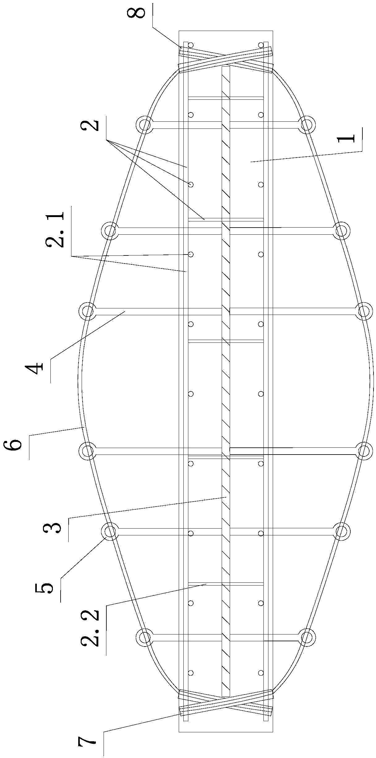
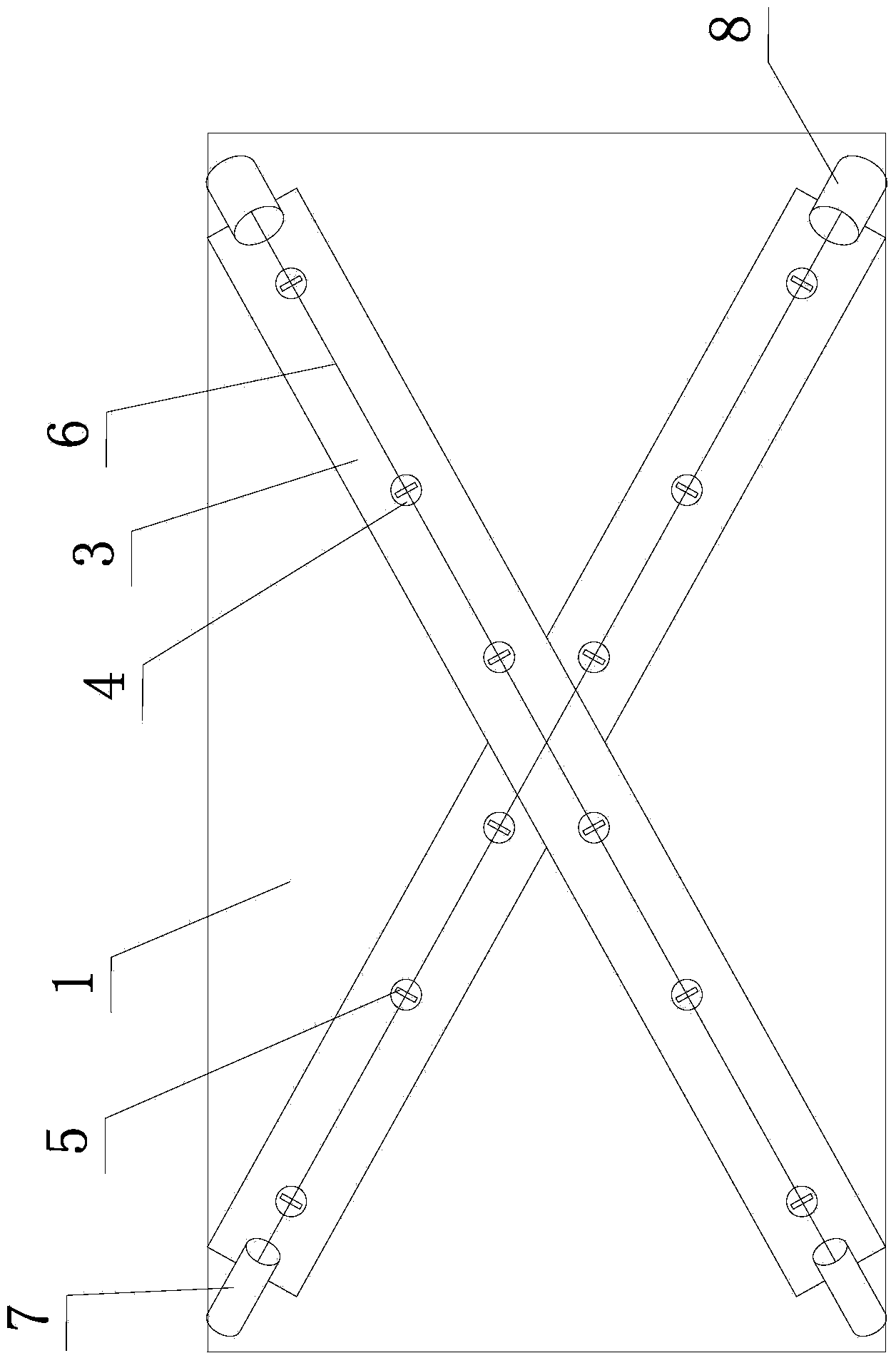
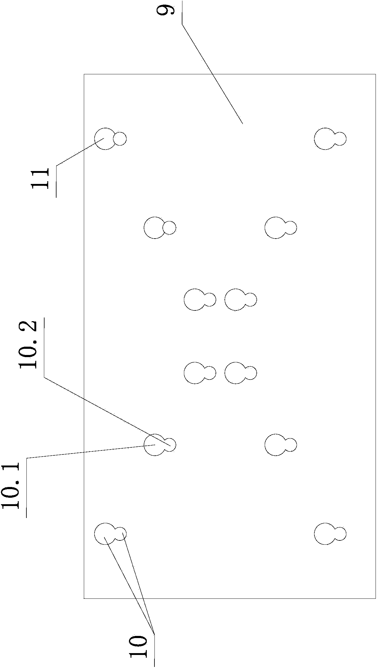
[0027] Such as figure 1 , figure 2 , image 3 , Figure 4 Shown, the shear wall of the present invention, it comprises wall body 1. A reinforcement cage 2 and two intersecting steel ribs 3 are anchored in the wall 1 , and both steel ribs 3 are fixed with the reinforcement cage 2 . The inner surface and the outer surface of each steel rib 3 are fixed such as welding multiple guide pillars 4, and the multiple guide pillars 4 on the same surface of the same steel rib 3 are arranged along the width bisector of the steel rib 3 In a row, the shear wall has two steel ribs 3, and each steel rib 3 has two inner and outer surfaces, so that the shear wall has four rows of guide columns 4 in total. In every row of guide pillars 4, the guide pillars 4 in the middle are long and the guide pillars 4 on both sides are short, so as to form the bow-string ...


PUM


Abstract

The invention discloses a shear wall and a construction method thereof. The shear wall comprises a wall body (1); a steel cage (2) and two steel rib plates (3) are anchored in the wall body (1); each surface of each steel rib plate (3) is fixed to a row of guide posts (4), the outer ends of the guide posts (4) extend out of the wall body (1) and are provided with pull rings (5) fixedly, a tension cable (6) penetrates each of the pull rings (5) of the guide posts (4), and the anchoring ends and tensile ends of the cables (6) are anchored into the concrete of the wall body (1). The construction method includes penetrating each pull ring (5) of the guide posts (4) with one cable (6), penetrating a first tube (7) through the anchoring end of the cable (6), penetrating a second tube (8) through the tensile end, and tensioning the cable (6). By the aid of the shear wall and the construction method thereof, the horizontal bearing capability can be improved.

Description

technical field [0001] The invention relates to the construction technology of structural walls in the field of civil engineering, in particular to a shear wall and a construction method thereof. Background technique [0002] Shear walls refer to walls added in buildings to resist horizontal shear forces. Because the horizontal shear force that high-rise buildings have to resist is mainly caused by earthquakes, shear walls are also called seismic walls. The shear wall is a reinforced concrete structure. In order to enhance the strength and rigidity of the shear wall, in addition to the conventional steel cage, two intersecting steel ribs will be anchored in the wall concrete. The two steel ribs are connected with the steel cage. Connection, from the thickness direction of the wall, the two steel ribs are roughly located in the middle of the thickness of the wall, from the wall direction of the wall, the width bisector of each steel rib and a diagonal line of the wall coinc...

Claims


Application Information

Patent Timeline
Patent Type & Authority Applications(China)
IPC IPC(8): E04B2/58E04G21/00
Inventor 查支祥叶文亚彭卫
Owner NINGBO INST OF TECH ZHEJIANG UNIV ZHEJIANG
Why Eureka
Try Eureka