Metal plate stamping die

A technology for stamping dies and metal sheets, applied in metal processing equipment, forming tools, manufacturing tools, etc., can solve the problem of inability to clean up waste in the lower die seat, and achieve the effects of preventing adhesion, tight coordination, and improving work efficiency.

Active Publication Date: 2021-10-08
南通炜冠机械模具有限公司
View PDF7 Cites 6 Cited by
  • Summary
  • Abstract
  • Description
  • Claims
  • Application Information

AI Technical Summary

Problems solved by technology

[0005] The purpose of the present invention is to provide a sheet metal stamping die for the obvious limitations of the workpiece fixing method and the inability to clean the waste in the lower die seat proposed in the above background technology

Method used


Image

  • Metal plate stamping die
  • Metal plate stamping die
  • Metal plate stamping die

Examples


Embodiment Construction

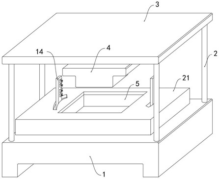
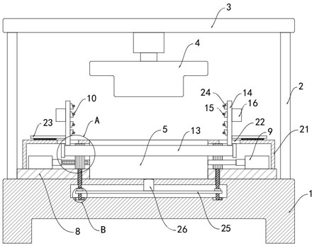
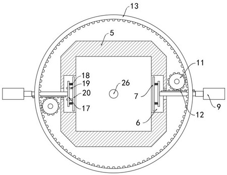
[0028] Such as Figure 1-6 As shown, a sheet metal stamping die includes a base 1, a pillar 2 and a top plate 3, an upper die 4 is installed on the top plate 3, and a stamping cylinder is arranged between the upper die 4 and the top plate 3 to drive the upper die 4 to move down Stamping, the base 1 is provided with a lower mold base 5 matching the upper punch 4, and both sides of the lower mold base 5 are provided with chute 6, and a clamping assembly 7 slides in the chute 6, and the two sides of the lower mold base 5 Both are provided with mounting base 8, on which hydraulic cylinder 9 is fixed, and the output end of hydraulic cylinder 9 is connected with clamping assembly 7, and the position of clamping assembly 7 can be controlled by controlling the expansion and contraction of hydraulic cylinder 9, that is, to realize the The metal plates of different specifications and sizes are fixed, and the base 1 is provided with a chip removal mechanism 10 .

[0029] The chip remova...


PUM


Abstract

The invention belongs to the technical field of dies, and particularly relates to a metal plate stamping die. The metal plate stamping die comprises a base, support columns and a top plate, wherein an upper stamping die is installed on the top plate; a lower die holder matched with the upper stamping die is arranged on the base; sliding grooves are formed in the two sides of the lower die holder; clamping assemblies are arranged in the sliding grooves in a sliding manner; mounting seats are arranged at the two sides of the lower die holder; hydraulic cylinders are fixed to the mounting seats, and the output ends of the hydraulic cylinders are connected with the clamping assemblies; a scrap removing mechanism is arranged on the base, the scrap removing mechanism comprises tooth columns rotationally connected to the mounting seats; the output ends of the hydraulic cylinders are connected with racks; the racks are meshed with the tooth columns; and a rotating ring is arranged outside the lower die holder. According to the metal plate stamping die, metal plates of different specifications and sizes can be fixed, air is injected into the lower die holder in multiple directions through spray heads, wastes at the corners in the lower die holder are completely removed, and the metal plates in the lower die holder can be automatically jacked up after stamping is completed through the arrangement of ejection columns.

Description

technical field [0001] The invention belongs to the technical field of dies, and in particular relates to a sheet metal stamping die. Background technique [0002] The stamping die uses the die installed on the press to apply pressure to the material to cause separation or plastic deformation. In industrial production, with the improvement of the quality requirements of the metal sheet, it is necessary to stamp and shape the metal sheet through the stamping die. [0003] After searching, the national patent publication number is CN110340233B, which discloses a sheet metal stamping die, including a base, a top seat and a pillar; one end of the pillar is fixedly connected with the base, and the other end is fixedly connected with the top seat, and a transverse Rod; also includes upper top plate, No. 1 cylinder, upper die, lower die seat, drive unit, clamping unit and controller; drive unit includes No. 1 rope, turntable, No. 1 shaft, No. 1 screw and slider; clamp The tighteni...

Claims


Application Information

Patent Timeline
Patent Type & Authority Applications(China)
IPC IPC(8): B21D37/10B21D43/00B21D45/04B08B5/02B08B13/00F16F15/067
CPCB21D37/10B21D43/003B21D45/04B08B5/02B08B13/00F16F15/067
Inventor 李卫建
Owner 南通炜冠机械模具有限公司
Why Eureka
Try Eureka