Anti-blockage flow guide expansion joint

An expansion joint, anti-clogging technology, applied in the field of expansion joints, to achieve the effect of high reliability, not easy to damage, and improve service life

Active Publication Date: 2015-01-21
WUHUAN ENG
View PDF7 Cites 3 Cited by
  • Summary
  • Abstract
  • Description
  • Claims
  • Application Information

AI Technical Summary

Problems solved by technology

[0004] The purpose of the present invention is to solve the above technical problems, to provide a simple structure, easy installation and maintenance, high reliability, local deceleration or speed up of the conveying medium, and diversion, so that the conveying medium can pass through the expansion joint quickly and smoothly. , effectively prevent solid particles from accumulating in the dead zone of the expansion joint and blockage, and improve the service life of the expansion joint.

Method used


Image

  • Anti-blockage flow guide expansion joint
  • Anti-blockage flow guide expansion joint
  • Anti-blockage flow guide expansion joint

Examples


Embodiment 1

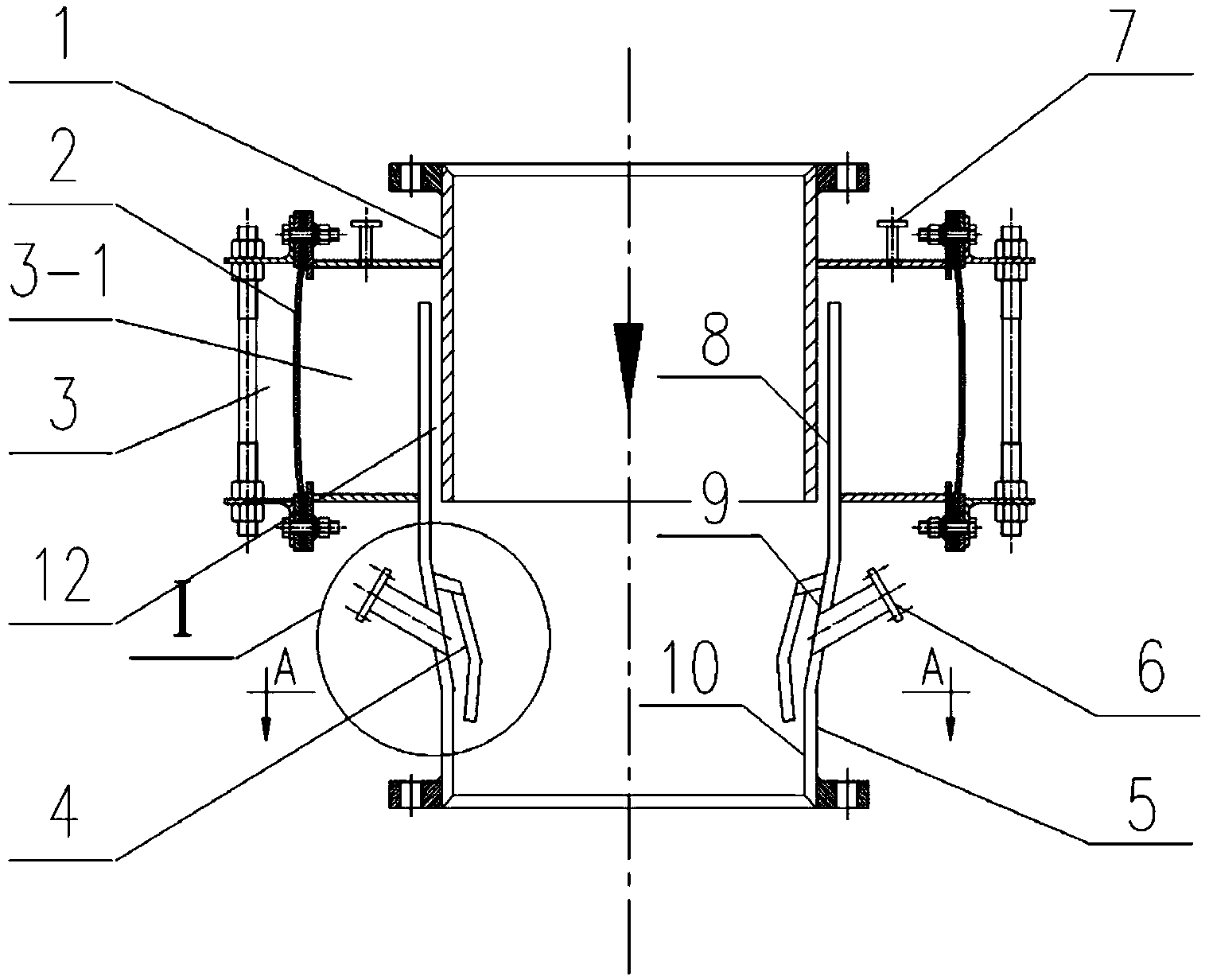
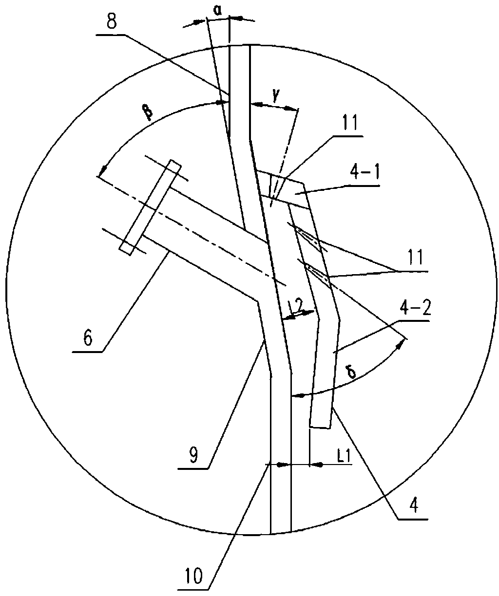
[0038] Embodiment 1: refer to Figure 1 to Figure 4 , the lower part of the inner ring 1 is fitted with the upper part of the outer ring 5, the outer ring 5 is composed of the upper part 8 of the outer ring, the middle part 9 of the outer ring and the lower part 10 of the outer ring, wherein the diameter of the lower part 10 of the outer ring is smaller than the diameter of the upper part 8 of the outer ring , the inclination angle α of the pipe wall in the middle part of the outer ring is 5-30°, and the sealing device 3 equipped with a non-metallic fabric skin 2 (or metal bellows) is installed on the outer part of the sleeve, and the non-metallic The sealed cavity 3-1 inside the fabric skin 2 is connected with a sealed tube 7, and the sealed cavity 3-1 communicates with the cavity in the outer ring 5 through the gap 12 where the inner ring 1 and the outer ring 5 are fitted. The gap between ring 1 and outer ring 5 is controlled at 1-20mm. A plurality of guide tubes 6 are conn...

Embodiment 2

[0046] Except that the guide device is different from that in embodiment 1, all the others are the same as in embodiment 1. The flow-guiding device is a flow-guiding inner tube 13 installed on the inner wall surface of the outer ring middle part 9, the inlet of the flow-guiding inner tube 13 communicates with the outlet of the flow-guiding tube 6, and the flow-guiding inner tube 13 The outlet of the outlet is vertically downward along the wall surface of the outer ring 5. Further, a plugging port 11 may also be provided on the flow guiding inner tube 13 as required. The diversion wind drawn from the diversion pipe 6 is drawn out through the outlet of the blowing plugging port 11 and the diversion inner pipe 13 .


PUM


Abstract

The invention discloses an anti-blockage flow guide expansion joint which solves the problems of easy blockage, easy leakage and damage, poor reliability and short service life of an existing expansion joint. According to the technical scheme, the anti-blockage flow guide expansion joint comprises an inner ring and an outer ring; the lower part of the inner ring and the upper part of the outer ring are arranged in a sleeving manner; a sealing device made of nonmetal textile skin or a metal corrugated pipe is arranged outside the sleeved mounting part; multiple flow guide pipes are connected to the pipe wall of the middle part of the outer ring; a flow guide device is correspondingly arranged at the outlets of the flow guide pipes. The anti-blockage flow guide expansion joint is simple in structure, convenient and simple to install and maintain and high in reliability, can guide a conveyed medium, efficiently prevents solid particles from being gathered and blocked at a dead zone of the expansion joint.

Description

technical field [0001] The invention relates to an expansion joint for gas-solid two-phase flow. Background technique [0002] Expansion joints have been widely used in various fields such as petroleum, chemical industry, electric power, and metallurgy. The technology is mature and the use effect is good. Ordinary expansion joints usually have the functions of vibration reduction and displacement absorption. , the outer part of the suit is equipped with a sealing device equipped with a non-metallic fabric skin or a metal bellows, and the sealing cavity of the sealing device is filled with fillers such as fiber fabric and thermal insulation cotton for vibration reduction and displacement absorption. This structure is easy to cause the gas-solid two-phase flow to easily generate eddy current phenomenon in the local area when the gas-solid two-phase flow passes through the contraction section in the middle of the expansion joint. Under the continuous washing of the conveying me...

Claims


Application Information

Patent Timeline
Patent Type & Authority Applications(China)
IPC IPC(8): F16L27/12F16L55/24
CPCF16L27/12F16L55/24
Inventor 胡建勋张洪伟章安杰刘三军汪明华蔡晓峰孙玉霞姜霞孟欢欢
Owner WUHUAN ENG
Why Eureka
Try Eureka