A combined water tray and air conditioner

A water tray and combined technology, which is applied in the direction of heating, condensation prevention, space heating and ventilation details, etc., can solve the problem that the water tray cannot be ventilated

Active Publication Date: 2017-05-03
GREE ELECTRIC APPLIANCES INC
View PDF4 Cites 0 Cited by
  • Summary
  • Abstract
  • Description
  • Claims
  • Application Information

AI Technical Summary

Problems solved by technology

[0006] An object of the present invention is to propose a combined water tray to solve the problem that the bottom of the water tray cannot be ventilated in the prior art, so that the water tray can also realize the air conditioning system while realizing the storage of condensed water. The wind in it can pass through it from all directions

Method used


Image

  • A combined water tray and air conditioner
  • A combined water tray and air conditioner
  • A combined water tray and air conditioner

Examples


Embodiment 1

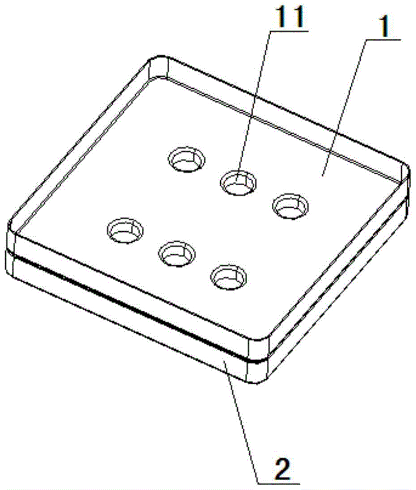
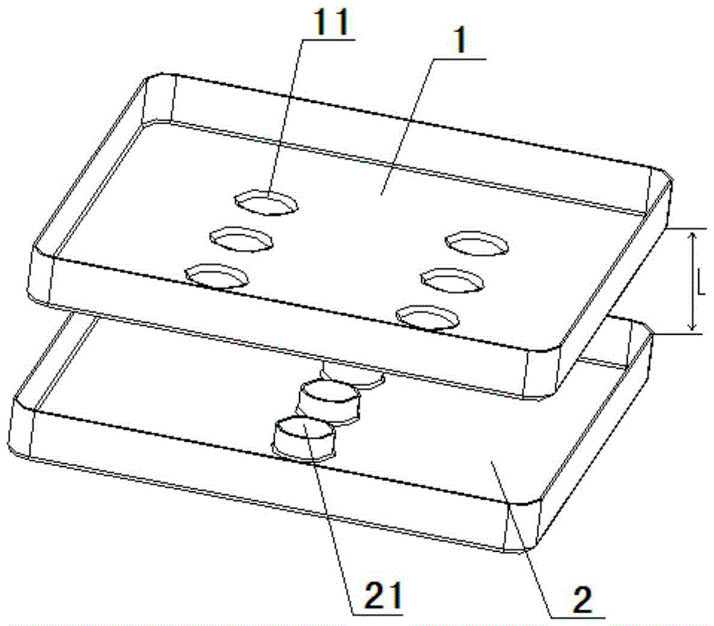
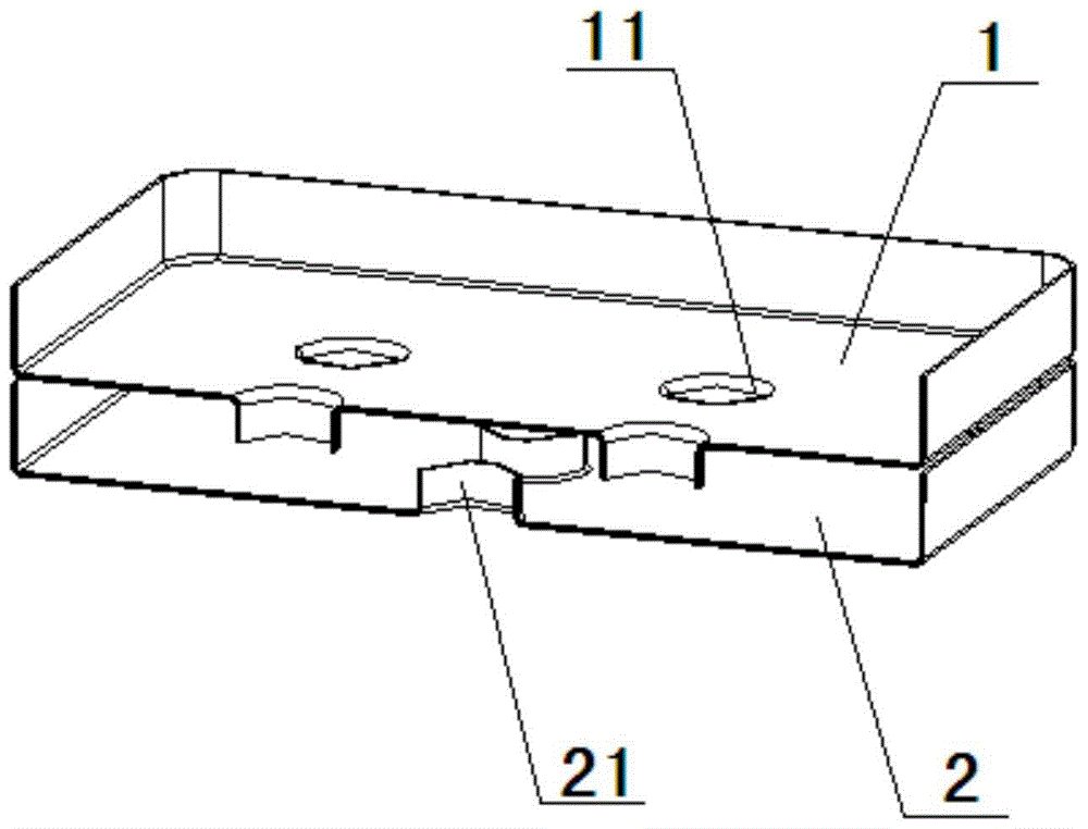
[0037] Such as Figure 1-Figure 7 As shown, it is a combined water receiving tray proposed in this embodiment. The combined water receiving tray has a two-layer structure, including a top water receiving tray 1 and a bottom water receiving tray 2. The top water receiving tray 1 is located at the bottom to receive water. plate 2 above.

[0038] Such as image 3 As shown, the top water tray 1 is provided with a first through hole 11 for the condensed water falling from the heat exchanger to flow from the top water tray 1 into the bottom water tray 2, and the bottom water tray 2 Ventilation holes 21 are provided for allowing wind to enter the bottom water tray 2 , and the first through holes 11 and the ventilation holes 21 are arranged staggered from each other. The specific meaning of the mutual staggering mentioned in the present invention is that under normal use conditions, the projection of the first through hole 11 on the bottom drain tray 2 and the ventilation hole 21 ca...

Embodiment 2

[0049] Such as Figure 8 As shown, it is a combined water tray structure proposed in this embodiment, including a top water tray 1 and a bottom water tray 2, the top water tray 1 is provided with a first through hole 11, and the bottom water tray 2 Ventilation holes 21 are arranged on the top, and bottom drain outlets 22 are arranged at the bottom of the side wall of the bottom water tray 2 . The difference between this embodiment and Embodiment 1 is that, in this embodiment, a top drain port 12 is also provided at the bottom of the side wall of the top water tray 1 . The setting of the top drain port 12 can share the workload of the bottom drain port 22 to a certain extent, so that a part of condensed water can be discharged from the top drain port 12, and prevent the bottom water tray 2 from being drained from the ventilation port due to too much condensed water. 21 overflows.

Embodiment 3

[0051] This embodiment proposes a combined water receiving tray, including a top water receiving tray and a bottom water receiving tray near the heat exchanger. The first through hole of the water receiving tray, the bottom of the water receiving tray is provided with a ventilation hole for air to pass through. The difference between this embodiment and the first embodiment is that it further includes a middle water receiving tray arranged between the top water receiving tray and the bottom water receiving tray. The middle water tray is provided with a second through hole for guiding the condensed water to the bottom water tray, and the second through hole may or may not be a flanging hole. When the second through hole is a flange hole, the flange of the second through hole faces the same direction as the direction of gravity.

[0052] In this embodiment, the positional relationship between the first through hole on the top water receiving tray and the second through hole on ...


PUM


Abstract

The invention relates to the field of air conditioners, and discloses a combined type water pan and an air conditioner. The combined type water pan comprises a top water pan body and a bottom water pan body, wherein the top water pan body is positioned above the bottom water pan body; the top water pan body is provided with first through holes; by the first through holes, water can flow to the bottom water pan body from the top water pan body; the bottom water pan body is provided with an air vents; by the air vents, air can enter the bottom water pan body; the air vent is an edge-turned hole; a turned edge of the air vent faces the reverse direction of the gravity; and the first through hole and the air vent are staggered from each other. The combined type water pan has a two-layered structure; the top water pan body is close to a heat exchanger and is mainly used for containing condensate water flowing from the heat exchanger; and the bottom water pan body is positioned below the top water pan body, is provided with the air vents, and the air vents are mainly used for guiding air of the bottom of the water pan to the inside of the water pan. By the water pan, water can be collected, and air can be fed, so that air in an air conditioner system can penetrate in the various directions of the water pan.

Description

technical field [0001] The invention relates to the field of air conditioners, and more specifically discloses a combined water tray and an air conditioner. Background technique [0002] When the water tray is used in the air conditioning system, it is used to receive the condensed water generated during the use of the heat exchanger. The water receiving tray in the prior art is generally located under the heat exchanger (here, the heat exchanger generally refers to a finned tube heat exchanger, and can also be other forms of heat exchanger), and is used to receive the heat exchanger from the heat exchanger. Condensed water falling from the device in the direction of gravity. The working principle of the water tray requires that the plane area of ​​the water tray is larger than the projected area of ​​the heat exchanger above it along the vertical direction on the water tray; The water receiving tray can hold a certain amount of water. [0003] There are two types of inst...

Claims


Application Information

Patent Timeline
Patent Type & Authority Patents(China)
IPC IPC(8): F24F13/22
CPCF24F13/222
Inventor 施正兴周剑波安杰龚立选林超魏书生王琦郭艳丽丁东青徐煌财孙宁廖翠波曾锦国牛朋涛何国军曹勇汪俊勇
Owner GREE ELECTRIC APPLIANCES INC
Why Eureka
Try Eureka