Building body ventilating device

A technology for ventilation devices and buildings, applied in ventilation systems, space heating and ventilation, household heating, etc., can solve the problems of no air guide, easy damage, waste of space, etc., and achieve space saving, convenient opening and simple structure. Effect

Inactive Publication Date: 2017-12-22
杨金燕
5 Cites 0 Cited by

AI-Extracted Technical Summary

Problems solved by technology

[0002] The general building ventilation structure adopts the structure of windows. There are many types of windows, such as push-open windows or movable windows, but the structure of push-open windows is prone to breakage and damage in windy weather, and is very easy to damage
Therefore, the aluminum alloy sliding window is the most used at present. It generally has two sides of glass when in use. Pushing one side of the glass t...

Abstract

The invention discloses a building body ventilating device. The building body ventilating device comprises a transparent plate installed at the position of a ventilating opening, a through ventilating cavity is formed in the middle of the transparent plate, the outer side end of the ventilating cavity is sealed through a movable plate, the outer side ends of the upper and lower ends of the transparent plate are each provided with a fixing plate, the opposite faces of the fixing plates are each provided with a sliding groove, a sliding block is installed in each sliding groove, a spring is installed in each sliding groove, each sliding block is installed in the corresponding sliding groove and is in contact with the end face of one side of the corresponding spring, the upper and lower ends of the movable plate is each provided with a rotating shaft, the rotating shafts are arranged at the middle portions of the upper and lower end faces of the movable plate, and the opposite faces of the sliding blocks are each provided with a rotating shaft hole. The building body ventilating device is simple in structure, the movable plates can be conveniently pushed outwards, the ventilating cavity is opened, and air inlet is achieved; and an air guide structure can be formed by rotating the movable plate, external airflow is guided to enter an indoor place, more space is saved by the ventilating manner in the aspect of opening manner, external space is reasonably used, space of a building body is not used, and opening is more convenient.

Application Domain

Lighting and heating apparatusVentilation systems

Technology Topic

AirflowEngineering

Image

  • Building body ventilating device
  • Building body ventilating device

Examples

  • Experimental program(1)

Example Embodiment

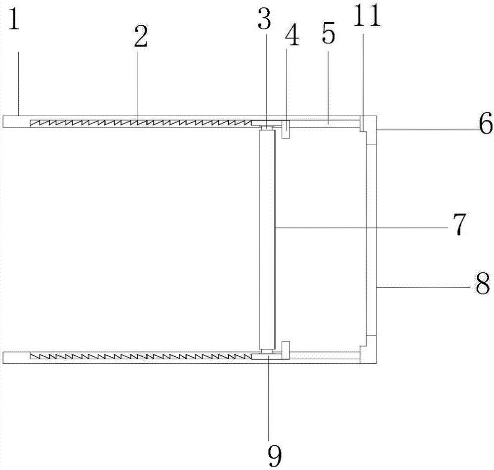
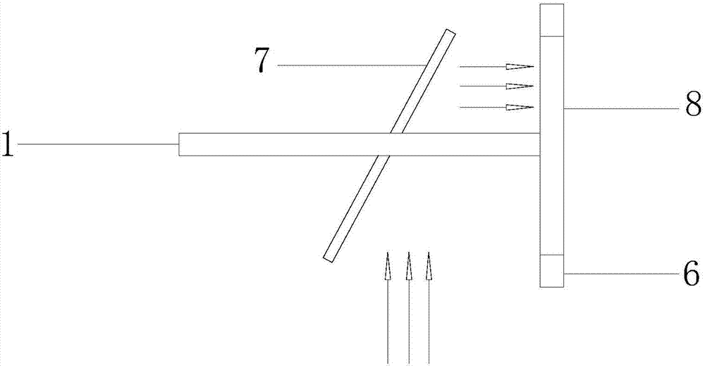
[0015] like figure 1 and figure 2 As shown, the ventilation device of this building includes a transparent plate 6 installed at the vent. The middle of the transparent plate 6 has a penetrating air cavity 8. The outer end of the air cavity 8 is sealed by a movable plate 7. The transparent plate The outer end of the upper and lower ends of 6 is all vertically provided with a fixed plate 1, and the opposite surface of the fixed plate 1 is all provided with a chute 5, and a slide block 9 is all loaded into the chute 5, and a spring 2 is all loaded into the chute 5. , the slide block 9 is loaded into the chute 5 and contacts with one side end face of the spring 2, a rotating shaft 3 is arranged at the upper and lower ends of the movable plate 7, and the rotating shaft 3 is arranged in the middle of the upper and lower end faces of the movable plate 7, and the sliding block 9 A rotating shaft hole is arranged on the opposite surfaces, and the movable plate 7 is loaded into the rotating shaft hole of the slider 9 through the rotating shaft 3 .
[0016] Wherein, the movable plate rotates relative to the fixed plate through the rotating shafts at the upper and lower ends, and forms an air guiding cavity. like figure 2 As shown, the direction of the arrow in the figure is the airflow direction. If it is a traditional aluminum alloy window, it cannot guide the external airflow into the room. figure 2 The structure in the structure only needs to rotate the movable plate, so that the movable plate is inclined, so that the part of the movable plate can be in contact with the air flow, and the inclined structure guides the air flow into the ventilation cavity, thereby realizing the air intake.
[0017] The circle, movable plate 7 is a transparent plate, and its opposite side of the ventilation cavity is provided with a ring sealing ring, and the spring 2 in the chute compresses the movable plate on the transparent plate and seals the ventilation cavity. When not in use, the movable plate seals the ventilation cavity through the sealing ring to increase the sealing performance.
[0018] Circle, the bottom surface of chute is all not provided with more than one slot, is positioned at the slot of slide block one side and inserts a positioning flashboard 4, and positioning flashboard 4 limits the position of slide block 9 in the chute. The positioning insert is mainly to limit the position of the slider in the chute to prevent the slider from being pushed out by the spring.
[0019] In this embodiment, a sealed cavity 11 is provided on the end surface of the transparent plate opposite to the movable plate, and one end of the movable plate 7 is buckled into the sealed cavity 11 to seal the entire ventilation cavity. When the movable plate is not opened, it is partially buckled into the sealing cavity, which is beneficial to better sealing.
[0020] In this embodiment, the exterior of the rotating shaft 3 is covered with a silica gel layer, and the rotating shaft 3 is fastened and installed in the rotating shaft hole provided on the slider through the silica gel layer. In order to ensure that the position of the movable plate remains fixed after the rotation relative to the upper and lower fixed plates, it is necessary to increase the friction between the shaft and the hole of the shaft, so a silicone layer is provided outside the shaft so that the shaft can be tightly in contact with the hole of the shaft, and the movable plate Once turned it stays at an angle.
[0021] Wherein, the two fixed plates 1 and the transparent plate 6 are in an integrated structure, and the two fixed plates are respectively arranged perpendicular to the transparent plate. When we need to open the ventilation, we only need to push out the movable plate and insert the positioning plate to realize the positioning of the slider. The pushing distance can be pushed out according to the user. Push the board out as far as possible, and then rotate it 90 degrees so that the movable board is perpendicular to the ventilation cavity. At this time, the ventilation cavity can be fully opened to obtain the largest air intake cavity area.
[0022] The beneficial effect of the present invention is that the structure of the present invention is simple, and the movable plate can be easily pushed out and the ventilation chamber opened to realize the air intake, and a wind guiding structure can be formed by rotating the movable plate to guide the external airflow into the room, This ventilation method is more space-saving in the opening method, and the external space is rationally used, and the space of the building itself is not used, so it is more convenient to open.

PUM

no PUM

Description & Claims & Application Information

We can also present the details of the Description, Claims and Application information to help users get a comprehensive understanding of the technical details of the patent, such as background art, summary of invention, brief description of drawings, description of embodiments, and other original content. On the other hand, users can also determine the specific scope of protection of the technology through the list of claims; as well as understand the changes in the life cycle of the technology with the presentation of the patent timeline. Login to view more.

Similar technology patents

Body condition measuring device

InactiveUS20050234351A1simple structure
Owner:DENSO CORP

Magnetic cooling apparatus and control method thereof

ActiveUS20130180263A1simple structure
Owner:SAMSUNG ELECTRONICS CO LTD

Dual-Drivetrain of Power-Assist Vehicle

InactiveUS20100181130A1enhance uphill momentumsimple structure
Owner:CHOU WEN CHENG

Classification and recommendation of technical efficacy words

  • Simple structure
  • save space

Sharing system for air-conditioning coat

InactiveCN107440179ASimple structureeasy to wear
Owner:QINGDAO HAIER AIR CONDITIONER GENERAL CORP LTD

Feeding device of sorter of batteries plate

InactiveCN101357717ASimple structurecooperate well
Owner:NANJING NORMAL UNIVERSITY

Emergency parachuting device and method for multiple-rotor unmanned aerial vehicle

InactiveCN103895870Aavoid aircraft crashSimple structure
Owner:SOUTH CHINA AGRI UNIV +1

Multi-node management method and system

Owner:XFUSION DIGITAL TECH CO LTD

Chemiluminescence immunoassay device

InactiveCN104777321Asave spaceHigh detection throughput
Owner:TSINGHUA UNIV +1

Protective frame for mobile communication device

InactiveUS20130088815A1minimize size and weightsave space
Owner:TAER INNOVATION

Folding type aerial photography aircraft

InactiveCN105035303Areduce volumesave space
Owner:WUXI MIRACLE SCI & TECH CO LTD
Why Eureka
Try Eureka