Pneumatic main breaking electromagnetic valve

A solenoid valve and spool technology, applied in the field of 25kV electrified railway pneumatic vacuum circuit breaker, pneumatic main break solenoid valve, can solve the problems of poor reliability, difficult to popularize and apply, complex structure, etc., to achieve high reliability, simple and compact structure, easy-to-achieve effects

Pending Publication Date: 2022-04-29
BEIJING CED RAILWAY ELECTRIC TECH
View PDF0 Cites 0 Cited by
  • Summary
  • Abstract
  • Description
  • Claims
  • Application Information

AI Technical Summary

Problems solved by technology

[0004] Solenoid valves in the prior art have complex structures, poor reliability, and are difficult to be popularized and applied in large quantities

Method used


Image

  • Pneumatic main breaking electromagnetic valve
  • Pneumatic main breaking electromagnetic valve
  • Pneumatic main breaking electromagnetic valve

Examples


Embodiment 1

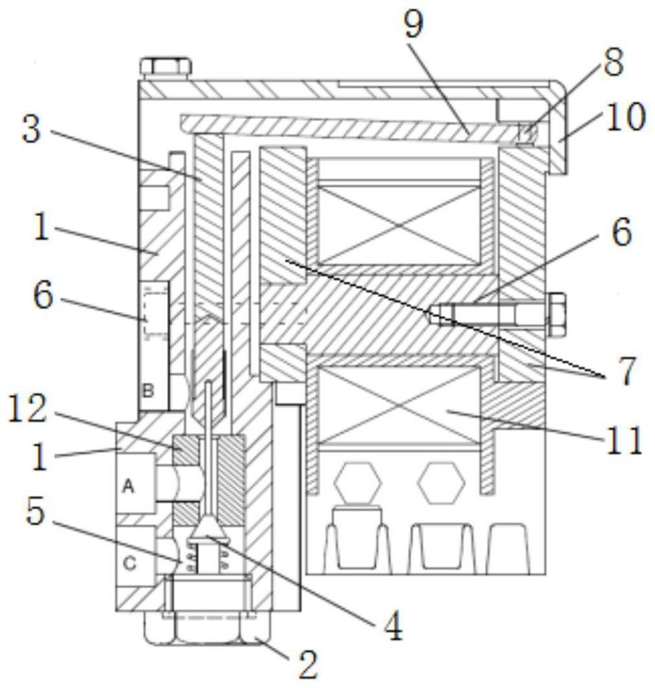
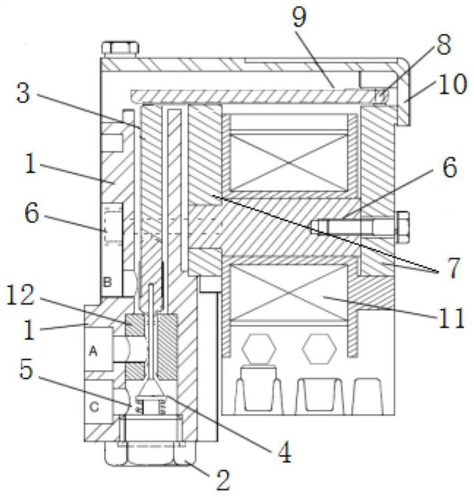
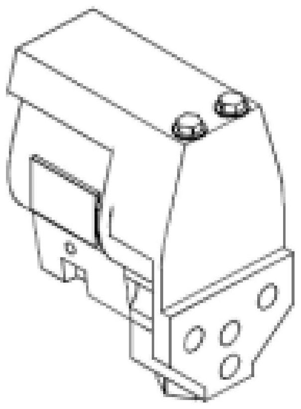
[0046] Such as figure 1 , figure 2 , image 3 As shown, the solenoid valve is assembled in the vacuum circuit breaker (such as figure 1 ),include:

[0047] Valve body 1, screw plug 2, upper valve core 3, lower valve core 4, spring 5, fastening screw 6, static armature 7, pin 8, moving armature 9, cover 10, coil 11, valve seat 12, air circuit Part of the air inlet C, the air outlet A is on the valve seat 12, and the air outlet B is on the valve body 1. The valve body 1 and the cover 10 form the main structure of the solenoid valve. The static armature 7, the moving armature 9, and the coil 11 are packaged inside the valve body 1. The fastening screw 6 fixes the static armature 7 on the valve body 1. The spring 5 is compressed and assembled. At the bottom of the lower spool 4, the lower spool 4 and the upper spool 3 are plugged and assembled, and the screw plug 2 is assembled at the bottom of the valve body 1, and is used to block the air inlet air path. The pin 8 fixes the...


PUM


Abstract

The invention discloses a pneumatic main breaking electromagnetic valve which comprises a valve body 1, a plug 2, an upper valve element 3, a lower valve element 4, a spring 5, a fastening screw 6, a static armature 7, a pin 8, a movable armature 9, a blocking cover 10, a coil 11 and a valve seat 12. The valve element assembly comprises an upper valve element 3, a lower valve element 4, a spring 5 and a valve seat 12. The valve seat 12 is provided with an axial through hole and a side hole to form a three-way hole piece. And the air path part comprises an air inlet C, an air outlet A and an air outlet B which respectively correspond to a bottom hole, a side hole and a top hole of the valve seat 12. The upper valve element 3 and the lower valve element 4 are arranged at the upper end and the lower end of the valve seat 12 respectively, the lower valve element 4 and the upper valve element 3 penetrate through an axial through hole of the valve seat 12 and then are assembled in an inserted mode, the spring 5 is assembled at the bottom of the lower valve element 4 after being compressed, and the plug 2 is assembled at the bottom of the valve body 1 and abuts against the spring 5. The air outlet A is connected with a main cylinder, the air inlet C is connected with an external high-pressure air source, and the air outlet B is emptied. The electromagnetic valve air path valve is controlled through external power supply and power failure, switching of an air supply air path and an air exhaust air path in the electromagnetic valve is achieved, and therefore air inlet and air exhaust of high-pressure air in the main air cylinder are achieved, and closing and breaking operation of the circuit breaker is achieved. The electromagnetic valve is simple and compact in overall structure, high in reliability and capable of being widely applied.

Description

technical field [0001] The invention relates to a rail vehicle vacuum circuit breaker, in particular to a pneumatic main break electromagnetic valve, which is used for a 25kV electrified railway pneumatic vacuum circuit breaker. Background technique [0002] Vacuum circuit breakers are suitable for all types of electric locomotives and motor vehicles with main line AC 25kV. It is installed on the roof of locomotives and motor cars or inside the high-voltage box. It is very important and directly affects the normal operation of the train. When the train starts to run, it is necessary to close the circuit breaker to connect to the catenary. When the train needs to split the phase or remove the fault, the vacuum circuit breaker needs to cut off the circuit between the vehicle and the catenary, so as to protect the electrical equipment of the vehicle. To disconnect, the input and discharge of high-pressure air must be switched through the solenoid valve to realize the movement ...

Claims


Application Information

Patent Timeline
Patent Type & Authority Applications(China)
IPC IPC(8): F16K11/044F16K31/06F16K27/02
CPCF16K11/044F16K31/0627F16K27/0263
Inventor 侯健伟王俊峰姜赞徐玉峰王栋
Owner BEIJING CED RAILWAY ELECTRIC TECH
Why Eureka
Try Eureka