Layout design method of multi-star sensor configuration layout

A technology of star sensor and layout design, applied in instruments, navigation calculation tools, measurement devices, etc., can solve the problems of low design efficiency, inability to visually observe the relative relationship, and the design process is not quantified, and achieve the effect of improving efficiency.

Active Publication Date: 2015-01-21
AEROSPACE DONGFANGHONG SATELLITE
View PDF4 Cites 27 Cited by
  • Summary
  • Abstract
  • Description
  • Claims
  • Application Information

AI Technical Summary

Problems solved by technology

This design method of the star sensor support structure layout has the following disadvantages: (1) the design is not intuitive and the efficiency is low. When using this method to design the star sensor layout, it is impossible to directly observe the optical axis of the star sensor and the sun, the earth, etc. The relative relationship between objects and stars can only be verified afterwa

Method used


Image

  • Layout design method of multi-star sensor configuration layout
  • Layout design method of multi-star sensor configuration layout
  • Layout design method of multi-star sensor configuration layout

Examples


Embodiment Construction

[0027] The present invention will be described in detail below in conjunction with the accompanying drawings.

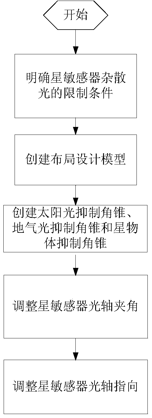
[0028] A kind of multi-satellite sensor configuration layout design method, its step is (as figure 1 ):

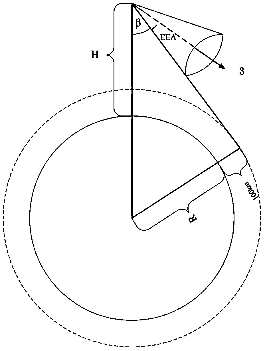
[0029] Step 1: Define the limiting conditions of the stray light of the star sensor, that is, define the minimum angles between the optical axis of the star sensor and the sunlight, the earth's atmosphere light and the star object, which are θs, θe, and θb respectively;

[0030] Sunlight rejection angle θ of star sensor S , Earth-atmospheric light suppression angle θ E , and the minimum angle θ between the stellar object e , the solar suppression angle θ must be guaranteed when the star sensor configuration layout S The sun cannot be seen in the interior, and the earth-atmospheric light suppression angle θ e The earth cannot be seen in the interior, and the minimum angle θ between it and the star object e No astral objects can be seen inside.

[0031] Step...


PUM


Abstract

The invention discloses a layout design method of a multi-star sensor configuration layout. The layout design method comprises the steps of (1) defining minimum included angles between an optical axis of a star sensor and sunlight, ground gas light and a star object; (2) creating a layout design model; (3) creating a sunlight inhibition pyramid, a ground gas light inhibition pyramid and a star object inhibition pyramid of each star sensor in a satellite stereo model; (4) adjusting the layout of each star sensor in real time on the satellite model; (5) adjusting the included angle between the optical axes of two star sensors from 20 theta s to 180 degrees, so that the included angle is greater than twice of a sunlight inhibition angle; and (6) rotating the star sensors, so that the relative movement of fixed stars is uniformly distributed on two coordinate axes which are perpendicular to the optical axis of each star sensor. By using the layout design method, the best attitude measuring precision of multi-star sensor attitude combined determination can be obtained, and the layout design efficiency of multiple star sensors is improved.

Description

technical field [0001] The invention relates to a multi-satellite sensor configuration layout design method, which belongs to the field of overall satellite design. Background technique [0002] Remote sensing satellites that use the principle of photogrammetry to locate ground targets need to obtain six outer azimuth elements of the satellite, that is, the position and attitude angle of the satellite. The position is called the outer azimuth line element, and the attitude angle is called the outer azimuth element. As the positioning accuracy of surveying and mapping satellite ground targets used in surveying and mapping, land survey and other applications is getting higher and higher, it is required to obtain high-precision outer azimuth elements and outer azimuth line elements. Currently, in order to obtain high-precision outer azimuth elements Generally, multiple (such as 3) high-precision star sensors are used on the satellite, and the configuration and layout design of ...

Claims


Application Information

Patent Timeline
IPC IPC(8): G01C21/20
CPCG01C21/025G01C21/20
Inventor 李岩霍德聪葛逸民李松明
Owner AEROSPACE DONGFANGHONG SATELLITE
Why Eureka
Try Eureka