Excavator linked control device

A technology of linkage control and excavator, which is applied to the layout, transportation and packaging of the control device and power device control mechanism, which can solve the problems of poor control accuracy and achieve the effect of wide application range

Pending Publication Date: 2019-02-26
山东帝盟重工机械有限公司
View PDF0 Cites 0 Cited by
  • Summary
  • Abstract
  • Description
  • Claims
  • Application Information

AI Technical Summary

Problems solved by technology

[0003] The invention proposes a novel excavator linkage control device for the problem of poor control accuracy of traditional electronic throttle and wheel chassis hydraulic system

Method used


Image

  • Excavator linked control device
  • Excavator linked control device
  • Excavator linked control device

Examples


Embodiment 1

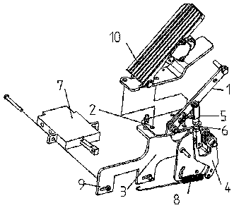
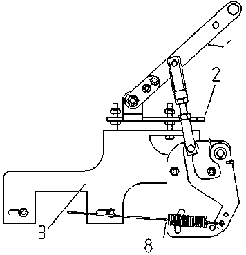
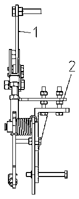
[0017] Example 1, such as Figure 1-Figure 7 As shown, this embodiment provides the specific structure of the excavator linkage control device, including the device body. Rod 6, clutch hydraulic valve 7 and clutch spring 8, the pressure plate support plate 2 and the base welding 3 are respectively located on the upper and lower sides of the bottom plate of the operating room and connected in series through bolts; The rod assembly 1 is hinged with the pressure plate support plate 2 through a pin with a hole, and the foot throttle assembly 4 is fixed to the base by welding 3, and the pressure rod assembly 1 and the foot throttle assembly 4 are cranked through the foot throttle fork 5 and screw rod 6. Rocker mechanism control; one end of the clutch spring 8 is connected to the lower end of the foot throttle assembly 4, and the other end is connected to the joystick of the clutch hydraulic valve 7. The foot throttle assembly 4 realizes the control of the clutch valve joystick thro...


PUM


Abstract

The invention belongs to the technical field of excavator devices, and relates to an excavator linked control device. A device body comprises a pressing rod assembly, a pressing rod supporting plate,a base welding part, an accelerator assembly, an accelerator fork, a lead screw, a clutch hydraulic valve and a clutch spring. The pressing rod supporting plate and the base welding part are located on the upper side and the lower side of an operation chamber bottom plate respectively and fixedly connected in series through a bolt. An accelerator pedal is arranged over the pressing rod assembly. The pressing rod assembly is hinged to the pressing rod supporting plate through a porous pin shaft. The accelerator assembly is fixed to the base welding part through a bolt. The pressing rod assemblyand the accelerator assembly are controlled by a crank rocker mechanism through the accelerator fork and the lead screw. One end of the clutch spring is connected with the lower end of the accelerator assembly, and the other end of the clutch spring is connected with a control rod of the clutch hydraulic valve. The accelerator assembly controls the clutch valve control rod through the clutch spring so that the on and off of the clutch hydraulic valve can be realized. Through the combination of the mechanical structures, the linkage and ratio control of the two independent parts including an electric induction accelerator and a hydraulic pilot control valve are realized.

Description

technical field [0001] The invention belongs to the technical field of excavator devices, and relates to an excavator linkage control device. Background technique [0002] During the operation of construction machinery such as hydraulic excavators, the electronic accelerator of the engine and the hydraulic system of the wheel and chassis are needed to realize the increase and decrease of the engine speed and the front and rear travel functions of the vehicle chassis. The electronic throttle and the wheel chassis hydraulic system are actually controlled by two separate actions, and cannot realize continuous associated proportional control, and the control accuracy is poor. Contents of the invention [0003] The invention proposes a novel excavator linkage control device aiming at the problem of poor control accuracy of the traditional electronic throttle and wheel chassis hydraulic systems. [0004] In order to achieve the above object, the present invention is achieved by...

Claims


Application Information

Patent Timeline
Patent Type & Authority Applications(China)
IPC IPC(8): B60K23/02B60K26/02
CPCB60K23/02B60K26/02
Inventor 王金铂张道秋樊磊李洋
Owner 山东帝盟重工机械有限公司
Why Eureka
Try Eureka