Liquid level display device

A display device and liquid level display technology, applied in buoy liquid level indicators, packaging, transportation and packaging, etc., can solve the problems of reducing the visual effect and affecting the normal operation of machinery and equipment, and achieve a wide range of popularization, liquid level reading Get fast and accurate results with less structural changes

Active Publication Date: 2015-01-21
GUANGXI YUCHAI MASCH CO LTD
View PDF7 Cites 2 Cited by
  • Summary
  • Abstract
  • Description
  • Claims
  • Application Information

AI Technical Summary

Problems solved by technology

However, when the liquid storage tank is arranged in a place with poor light, or is suspended at a higher position, it is difficult to directly observe through the U-shaped connecting pipe, and after a period of use, the inner wall and outer wall of the U-shaped connecting pipe will be damaged due to dirt. Affects and reduces the visual effect. When the liquid level inside the liquid storage tank does not meet the set requirements and is not found in time, it is easy to affect the normal operation of the machinery and equipment.

Method used


Image

  • Liquid level display device
  • Liquid level display device
  • Liquid level display device

Examples


Embodiment 1

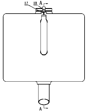
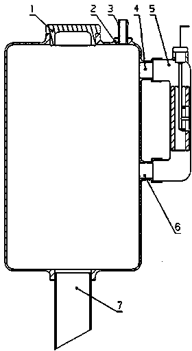
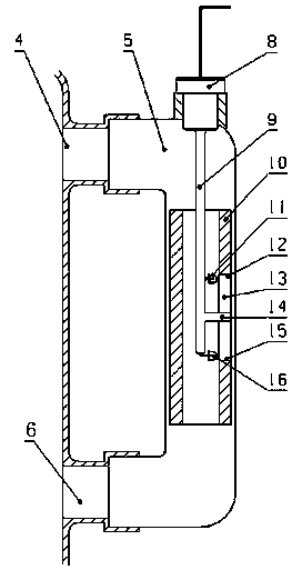
[0023] Example 1, such as figure 1 , figure 2 , image 3 , Figure 4 As shown, a liquid level display device of the present invention includes a liquid level display device body (5), which is installed on the outside of the liquid storage tank body (2), and the liquid storage tank body (2) includes a water outlet (7), a plug The cover (1), the drain port (3), and the water outlet (7) are connected with the working equipment to provide the working equipment with continuous pressure and supplement after liquid consumption. In the body (5) of the liquid level display device, an upper communicating water port (4) and a lower communicating water port (6) are provided, and a float (10) is provided at the same time. The float (10) is a middle-pass structure, and a side window (13) along the vertical direction is opened on the side of the float (10), and an upper edge (12) of the side window is provided above the side window (13), and a side window Window lower edge (15). A plug...

Embodiment 2

[0027]Embodiment 2, a liquid level display device, including a blocking cover, a liquid storage tank body, a drain port, an upper connecting water port, a display device body, a lower communicating water port, a water outlet, a plug, a wire installation rod, a float, a green light-emitting diode, The upper edge of the side window, the side window, the limit rod, the lower edge of the side window, the red light-emitting diode, the first wire, and the second wire are characterized in that there is a blocking cover (1) on the top of the liquid storage tank body (2), and a Drain port (3), there is a water outlet (7) under the liquid storage tank body (2), the display device body (5) is installed on the outer side of the liquid storage tank body (2), and the upper part of the display device body (5) is connected The water port (4) is connected to the liquid storage tank body (2), and there is a lower communication port (6) under the display device body (5) to communicate with the li...


PUM


Abstract

The invention discloses a liquid level display device. The liquid level display device is characterized in that the liquid level display device is installed on the outer side of a liquid storage tank and used to display the liquid level height in the liquid storage tank. The liquid level display device comprises a display device body, wherein the display device body is of a transparent structure made of glass or engineering plastic, a water gap communicated from top to bottom is arranged in the display device body, the water gap is communicated with the interior of a water tank, a floater is further arranged in the display device, the floater is a nontransparent device, the interior of the floater is of a hollow structure, a long-strip-shaped side window is formed in the side face of the floater, a red light emitting diode is arranged at the bottom of the internal hollow structure of the floater along the vertical direction, and a green light emitting diode is arranged at the top of the internal hollow structure of the floater along the vertical direction. The liquid level display device has the advantages of being compact in structure, and strong in practicability, and convenient to install, popularize and use.

Description

technical field [0001] The invention relates to a liquid level display device, in particular to a device for displaying liquid level height limit values ​​with two different colored lights. Background technique [0002] The existing liquid storage tank can display the liquid level inside the liquid storage tank through the principle and structure of the U-shaped connecting pipe. However, when the liquid storage tank is arranged in a place with poor light, or is suspended at a higher position, it is difficult to directly observe through the U-shaped connecting pipe, and after a period of use, the inner wall and outer wall of the U-shaped connecting pipe will be damaged due to dirt. The impact reduces the visual effect. When the liquid level inside the liquid storage tank does not meet the set requirements and is not found in time, it is easy to affect the normal operation of the machinery and equipment. Contents of the invention [0003] The technical problem to be solved ...

Claims


Application Information

Patent Timeline
Patent Type & Authority Applications(China)
IPC IPC(8): G01F23/30B65D90/48
Inventor 李宇果王迎红甘建华农薇徐伟
Owner GUANGXI YUCHAI MASCH CO LTD
Why Eureka
Try Eureka