Projection screen, its manufacturing method and method for controlling light with the projection screen

A technology of projection screen and light, which is applied in the field of projection screen, can solve the problems of unusable and limited usage conditions of the projector, and achieve the effect of low cost, low price and simple production process

Inactive Publication Date: 2016-04-27
杨作林
View PDF11 Cites 0 Cited by
  • Summary
  • Abstract
  • Description
  • Claims
  • Application Information

AI Technical Summary

Problems solved by technology

It cannot be used during the day when there is interference from ambient light
Therefore, the usage conditions of the projector are very limited

Method used


Image

  • Projection screen, its manufacturing method and method for controlling light with the projection screen
  • Projection screen, its manufacturing method and method for controlling light with the projection screen

Examples


Embodiment 1

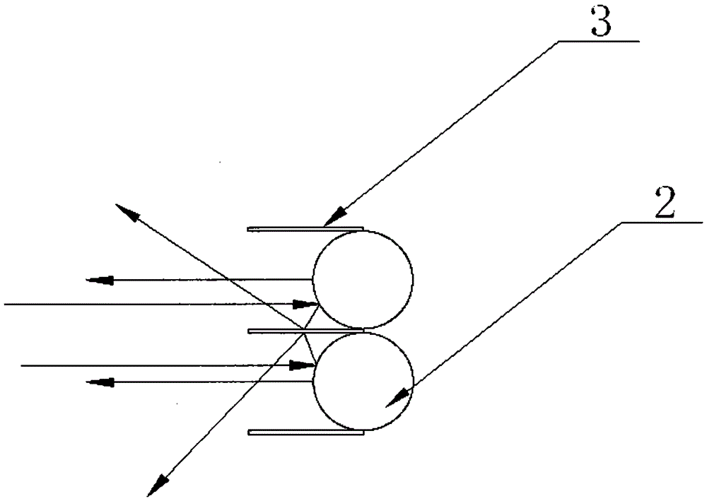
[0038] Such as figure 1 As shown, a projection screen includes a back film 1 arranged on the bottom surface, the upper surface of the back film 1 is covered with several convex mirrors 2 for reflecting light, and gaps are left between the sides of adjacent convex mirrors 2. The gap is filled with a light-blocking plate 3 that blocks light, and the light-blocking plate 3 extends outward perpendicular to the back film 1 to the light-transmitting film 4 . The light partition 3 blocks the light from around the projection screen and prevents the light from reaching the convex mirror 2. The light partition 3 is vertically attached to the film 1, and the projector is placed on the front of the projection screen. The light emitted by the projector It will pass smoothly through the gap between the light barriers 3 onto the convex mirror 2 without being blocked, and the light of the projector passes to the front of the projection screen through the reflection of the convex mirror 2; aga...

Embodiment 2

[0051] The projection screen described in this embodiment and the method for controlling light with the projection screen are the same as those in Embodiment 1, the difference lies in the manufacturing method of the projection screen. The manufacturing method of the present embodiment is as follows:

[0052] Rollers are used to press the back film 1 , the light barrier 3 and the convex mirror 2 ; and the pressed back film 1 , the light barrier 3 and the convex mirror 2 are fixedly connected. The manufacturing process is simple and the cost is low.

[0053] Using the synthetic production method, the honeycomb-shaped light-blocking plate 3 and the convex mirror 2 are respectively pressed and formed by corresponding rollers, and then the light-blocking plate 3 and the convex mirror 2 are respectively fixed on the back film 1, wherein: the light-blocking plate 3 The honeycomb holes are formed by a punching machine, and the convex mirror 2 is formed by an embossing machine to form ...


PUM


Abstract

The invention discloses a projection screen, a manufacturing method of the projection screen, and a method for controlling light rays by means of the projection screen. The projection screen comprises a back film arranged on the bottom surface, the upper surface of the back film is covered with a plurality of convex mirrors used for reflecting the light rays, a gap is reserved between side faces of every two adjacent convex mirrors, and light isolation boards used for shielding the light rays are arranged in the gaps and extend outwards in the direction perpendicular to the back film to a light-pervious film. The manufacturing method of the projection screen includes the steps that the back film, the light isolation boards and the convex mirrors are pressed by means of a roller and then are fixedly connected after being pressed. The method for controlling the light rays by means of the projection screen includes the following steps that (a) the light isolation boards are used for isolating ambient light emitted from the periphery of the projection screen, and (b) incoming projection light is reflected to the projection screen by means of the convex mirrors. The projection screen, the manufacturing method of the projection screen and the method for controlling the light rays by means of the projection screen have the advantages that the projection screen which can be used when the intensity of the ambient light is high is not limited by environment conditions; cost is low, resources are saved and industrial popularization is easy to achieve.

Description

technical field [0001] The invention relates to optical technology, in particular to a projection screen, a manufacturing method thereof and a method for controlling light with the projection screen. Background technique [0002] Projection screens are used in movies, offices, home theaters, and large conferences. A tool for displaying image and video files. Projection screens can generally be divided into two types: reflection type and transmission type; reflection type is used for front projection, and transmission type is used for rear projection; front projection screen is divided into flat screen and arc screen; Bead curtain, metal curtain, embossed plastic curtain, elastic curtain, etc. (embossed plastic is divided into white plastic, gray plastic, silver plastic, etc.). [0003] Screen gain technology; gain: It is a digital representation of the inherent reflection characteristics of the screen material (brightness at various angles). Project a certain amount of li...

Claims


Application Information

Patent Timeline
Patent Type & Authority Patents(China)
IPC IPC(8): G03B21/602G03B21/625B29C59/04
CPCG03B21/602G03B21/625
Inventor 杨作林
Owner 杨作林
Why Eureka
Try Eureka