Object detection method and device

An object detection and object technology, applied in the field of image processing, can solve the problems of difficult to detect objects, weak object features, and difficult to detect objects such as vehicles, and achieve the effect of reducing or eliminating deformation

Inactive Publication Date: 2015-01-21
RICOH KK
View PDF7 Cites 9 Cited by
  • Summary
  • Abstract
  • Description
  • Claims
  • Application Information

AI Technical Summary

Problems solved by technology

Due to the sparse disparity map effect, it may be difficult to detect objects such as vehicles, etc.
Moreover, in practice, it is often necessary to project the original disparity map horizontally or vertically to obtain a U disparity map or a V

Method used


Image

  • Object detection method and device
  • Object detection method and device
  • Object detection method and device

Examples


Embodiment Construction

[0021] Preferred embodiments of the present invention will be described in more detail below with reference to the accompanying drawings. Although preferred embodiments of the invention are shown in the drawings, it should be understood that the invention may be embodied in various forms and should not be limited to the embodiments set forth herein. Rather, these embodiments are provided so that this disclosure will be thorough and complete, and will fully convey the scope of the present invention to those skilled in the art.
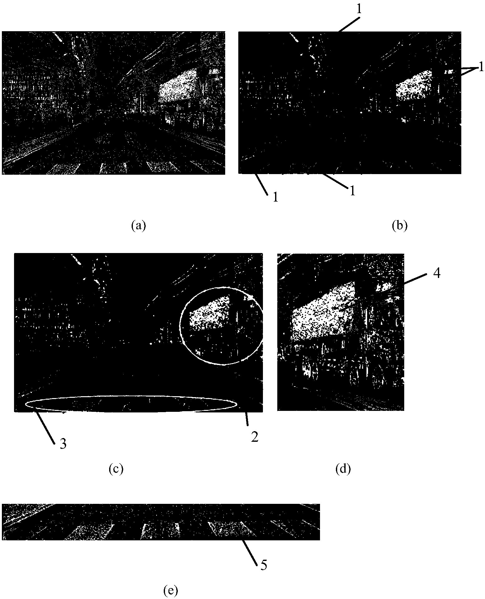
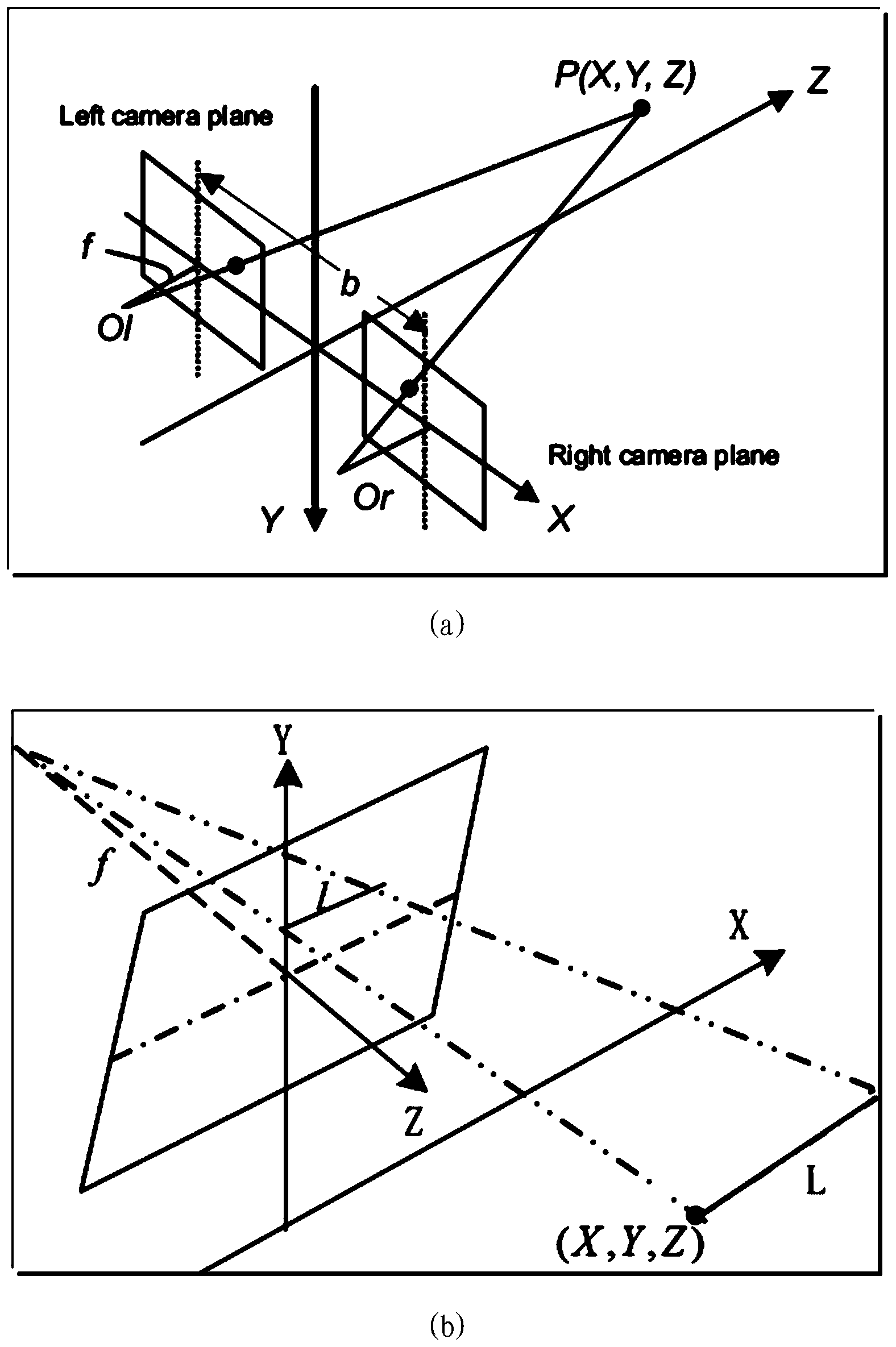
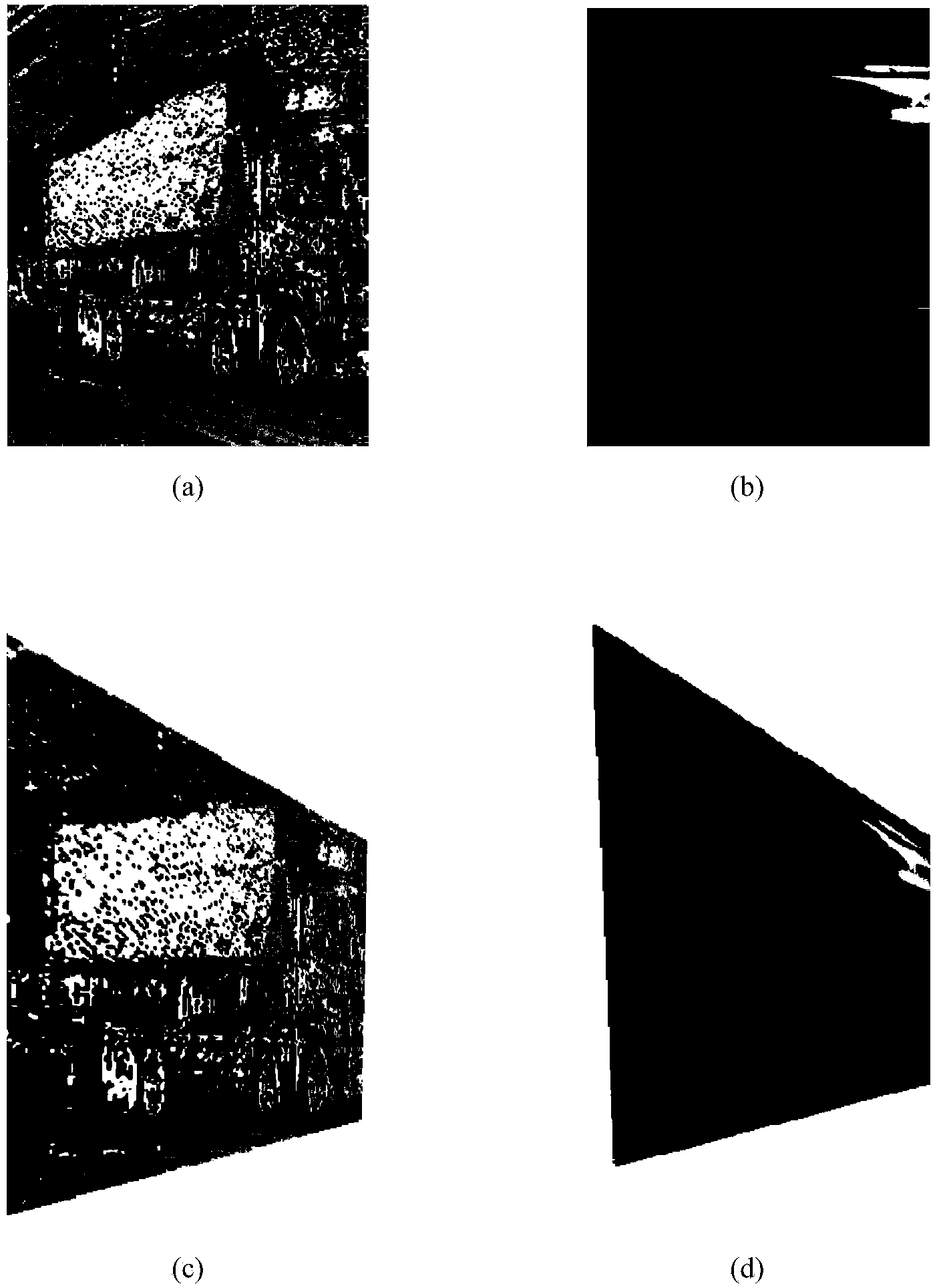
[0022] The main idea of ​​the present invention is to detect the plane from the disparity map, determine the surface candidate of the object to be detected from it, and convert such object surface candidate (disparity map or corresponding grayscale image) into a front view surface. In this way, the influence of the original deformation can be eliminated, and the existing previously extracted features without deformation can be used to detect objects bas...


PUM


Abstract

The invention provides an object detection method and a device. The object detection method comprises steps that: disparity images are acquired from a stereo camera for object area imaging; planes are detected from the disparity images; object surface candidates are selected from the planes detected from the disparity images according to characteristics of a physical surface of an object; the object surface candidates are converted into front view surfaces, and the front view surfaces are object surface images acquired by utilizing the stereo camera to shoot from a visual angle just pointing to the physical surface of the object; the object is detected at least partially on the basis of the front view surfaces after conversion. According to the method and the device, influence of original deformation can be eliminated, the object is detected by utilizing already-extracted non-deformation characteristics and/or a classifier and on the basis of the front view surfaces after conversion.

Description

technical field [0001] The present invention generally relates to image processing, and more particularly relates to a method and device for object detection based on disparity map image processing. Background technique [0002] Many methods for detecting objects based on disparity images have been developed, such as detecting vehicles, fences, etc. on the road based on disparity images. [0003] However, sometimes, due to factors such as the performance limitation of the camera or the characteristics of the scene itself, a disparity map with relatively sparse disparity points may be obtained, which is called a sparse disparity map hereinafter. Due to the sparse disparity map effect, it may be difficult to detect objects such as vehicles etc. Moreover, in practice, it is often necessary to project the original disparity map horizontally or vertically to obtain a U disparity map or a V disparity map, and then perform object detection on the U disparity map or V disparity map...

Claims


Application Information

Patent Timeline
IPC IPC(8): G06T7/00
CPCG06T7/97G06T2207/10012G06T2207/20081
Inventor 刘殿超刘媛师忠超鲁耀杰陈超
Owner RICOH KK
Why Eureka
Try Eureka