Hinge device
A technology for hinges and mounting parts, applied to door/window accessories, hinges with pins, hinges, etc., to achieve the effect of reducing the number of parts
- Summary
- Abstract
- Description
- Claims
- Application Information
AI Technical Summary
Problems solved by technology
Method used
Image

Examples
Embodiment Construction
[0074] The best mode for carrying out the present invention will be described below with reference to the accompanying drawings.
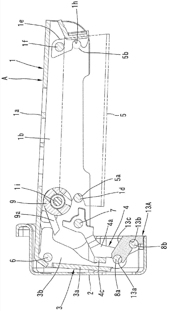
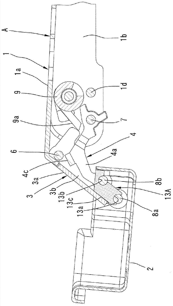
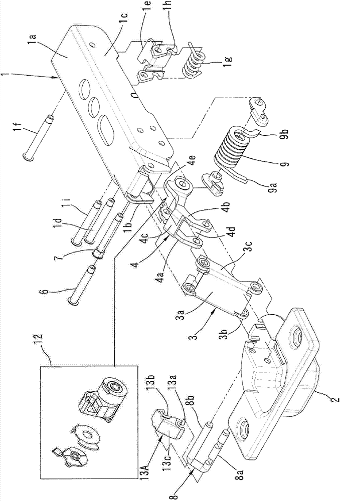
[0075] Figure 1 to Figure 7 The first embodiment of the present invention is given. The hinge device A of this embodiment has a main body 1 , an attachment 2 , and a pair of first and second links 3 and 4 .
[0076] The main body 1 is made of a metal plate, and consists of a rectangular plate-shaped main board 1a and a pair of side boards 1b, 1c protruding in the same direction from the long sides of the main board 1a at approximately right angles to each other. Formed, the cross section is roughly "コ" shape. The main body 1 is disposed near the inner opening of a frame with an opening (not shown), and its longitudinal direction is toward the depth of the frame (the direction connecting the opening and the inner part). For the convenience of description, in this embodiment, the frame body has an opening on its front portion; it is also assumed ...
PUM
 Abstract
Description
Claims
Application Information
 - Generate Ideas
- Intellectual Property
- Life Sciences
- Materials
- Tech Scout
- Unparalleled Data Quality
- Higher Quality Content
- 60% Fewer Hallucinations
Browse by: Latest US Patents, China's latest patents, Technical Efficacy Thesaurus, Application Domain, Technology Topic, Popular Technical Reports.
© 2025 PatSnap. All rights reserved.Legal|Privacy policy|Modern Slavery Act Transparency Statement|Sitemap|About US| Contact US: help@patsnap.com