
Fixture for clamping U-shaped inwardly bent sheet metal part

A technology of clamping tooling and internal bending, which is applied to metal processing equipment, auxiliary devices, feeding devices, etc., and can solve problems such as inconvenient clamping

Inactive Publication Date: 2015-01-28
PINGHU SIMAIKE MACHINERY MFG
View PDF10 Cites 9 Cited by
  • Summary
  • Abstract
  • Description
  • Claims
  • Application Information

AI Technical Summary

Problems solved by technology

[0002] Sheet metal parts are very common in the field of machinery manufacturing. They are usually used as accessories for some products. Generally, a large number of holes are processed on the surface of sheet metal parts for assembly. A finished sheet metal part may need to be punched through several processes. Or welding can be completed. In the middle, it is necessary to design tooling for the previous semi-finished sheet metal. U-shaped inner-bent sheet metal parts are very common in sheet metal parts. Because they are inner-bent, it is often inconvenient to clamp them.

Method used


Image

  • Fixture for clamping U-shaped inwardly bent sheet metal part
  • Fixture for clamping U-shaped inwardly bent sheet metal part
  • Fixture for clamping U-shaped inwardly bent sheet metal part

Examples


Embodiment Construction

[0015] The specific embodiments of the present invention will be further described below in conjunction with the drawings:

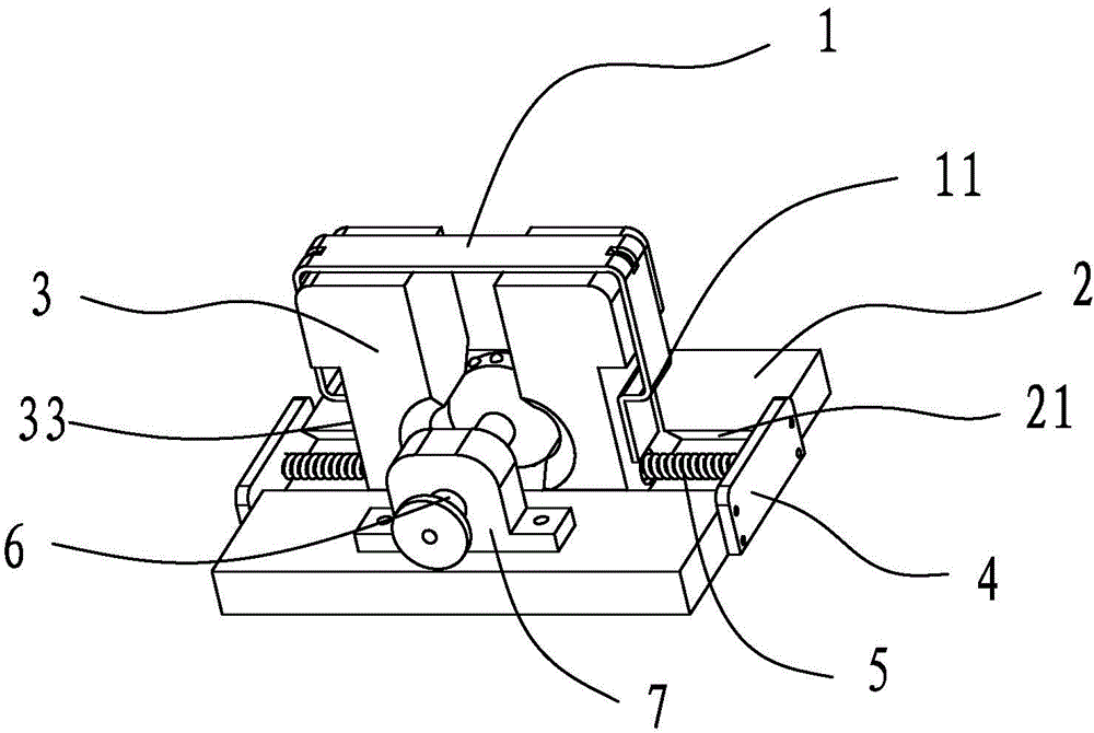
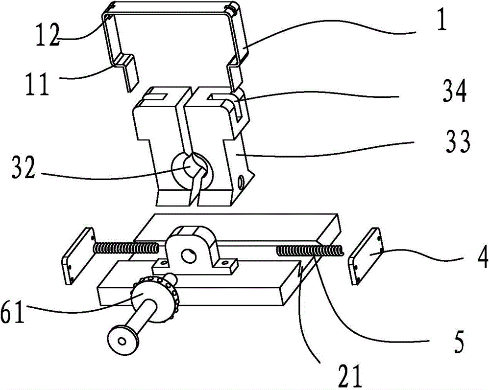
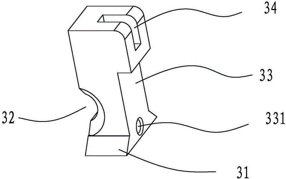
[0016] Such as Figure 1 to Figure 4 As shown, a U-shaped inner bending sheet metal clamping tool, the sheet metal 1 is U-shaped, two side wings are provided with inner bending parts 11, including a bottom plate 2, the bottom plate is provided with a dovetail chute 21, dovetail sliding There are two symmetrical clamping blocks 3 sliding in the groove, the bottom of the clamping block is a dovetail slider 31, the inner wall of the clamping block is provided with a semicircular hole 32, the edge of the semicircular hole is wedge-shaped, and the outer wall of the clamping block is provided There is a concave step surface 33, the inner bending part is accommodated in the concave space formed by the concave step surface, the bottom plate is fixed with the baffle 4 at both ends of the dovetail chute, and the baffle is provided between the concave step surface Th...


PUM


Abstract

The invention discloses a fixture for clamping a U-shaped inwardly bent sheet metal part. The sheet metal part is U-shaped and two wings of the sheet metal part are provided with inwardly bent parts; the fixture comprises a base plate; the base plate is provided with a dovetail chute; two symmetrically arranged clamping blocks slide in the dovetail chute; the bottoms of the clamping blocks are provided with dovetail sliders; the inner side walls of the clamping blocks are provided with semicircular holes; the edges of the semicircular holes are wedge-shaped; the outer side walls of the clamping blocks are provided with inwards concave step faces; the inwardly bent parts are accommodated in inwards concave spaces formed by the inwards concave step faces; the base plate is fixedly provided with baffles at two ends of the dovetail chute; springs are arranged between the baffles and the inwards concave step faces; a push rod for pushing the clamping blocks is inserted between the semicircular holes of the two clamping blocks; the middle of the push rod is provided with a tensioner ring sleeve; the fixture can quickly and accurately clamp the U-shaped inwardly bent sheet metal part.

Description

Technical field [0001] The invention relates to a clamping tool for U-shaped inner bending sheet metal parts. Background technique [0002] Sheet metal parts are very common in the field of mechanical manufacturing. They are usually used as accessories for some products. Generally, a large number of holes are processed on the surface of sheet metal parts for assembly. A finished sheet metal part may need to be stamped through several processes Or welding can be completed. In the middle, it is necessary to design tooling for the previous semi-finished sheet metal. U-shaped inner bending sheet metal parts are very common in sheet metal parts. Because they are inner bending, they are often inconvenient to clamp . Summary of the invention [0003] The technical problem to be solved by the present invention is to provide a clamping tool for U-shaped internally bent sheet metal parts, which can quickly and accurately clamp the U-shaped internally bent sheet metal parts. [0004] The tec...

Claims


Application Information

Patent Timeline
IPC IPC(8): B23K37/04B21D24/04
CPCB21D43/00
Inventor 杨玉良
Owner PINGHU SIMAIKE MACHINERY MFG
Learn More