Earphone charging box

A charging box and earphone technology, which is applied in earphone/earphone accessories, rechargeable batteries/devices, electrical components, etc., can solve the problems of product aesthetic impact, scratch earphones, high corrosion resistance requirements, etc., and achieve the convenience of earphone insertion and removal. smooth effect

Active Publication Date: 2018-11-23
GEER INTELLIGENT TECH CO LTD
View PDF9 Cites 6 Cited by
  • Summary
  • Abstract
  • Description
  • Claims
  • Application Information

AI Technical Summary

Problems solved by technology

[0002] Nowadays, more and more mobile phones remove the earphone hole in order to reduce the space, which promotes the great development of wireless earphones. The design and use of wireless earphones cannot be separated from the charging box. On the one hand, it also plays the role of connecting earphones and updating software. In order to realize these functions, several charging contacts are often set on the earphones. At present, two contacts are the mainstream, but with the improvement of customer requirements, two contacts Points often do not meet the need for software upgrades
[0003] For the demand for more contacts, different products have proposed different designs. Limited by the contact between the earphones and the charging box, most products design the contacts on the main body of the earphones. This design can facilitate the setting of the charging mechanism, but , the charging contacts set on the main body will frequently come into contact with skin sweat when worn, which requires high corrosion resistance, and at the same time, it also has a certain impact on the aesthetics of the product
There are also some designs where the contacts are designed on the earphone handle of the earphone, which can improve the appearance of the product and reduce contact with the skin when wearing it. However, the contacts set on the earphone handle will cause the earphone to be placed in the direction of contact with the contact The direction is vertical, and the elastic contacts on the charging box will scratch the surface of the earphones when the earphones are put in, and even more seriously, the earphones will be stuck, making the earphones unable to be plugged in and out, or even damaging the earphones

Method used


Image

  • Earphone charging box
  • Earphone charging box
  • Earphone charging box

Examples


Embodiment 1

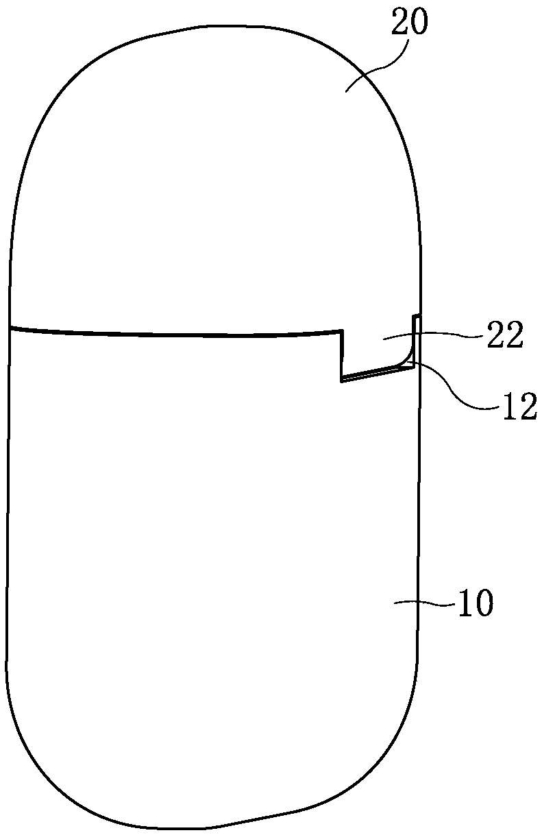
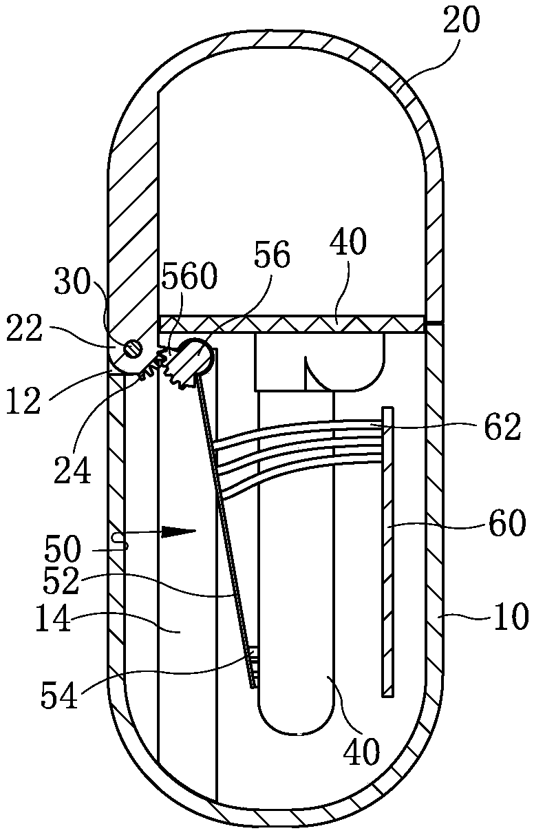
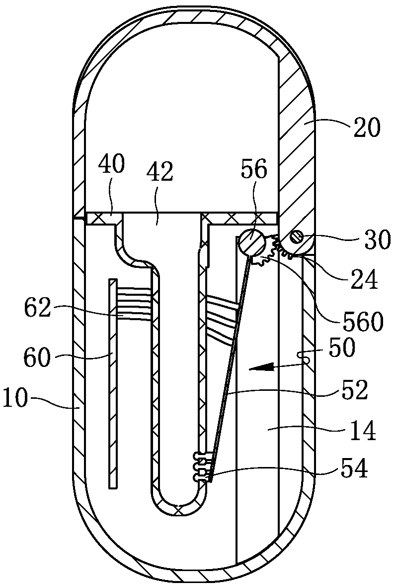
[0031] Such as figure 1 , figure 2 with image 3 As shown together, an earphone charging box includes a housing 10 and a cover 20 hinged together by a hinge shaft 30. An earphone receiving chamber 42 is arranged in the housing 10, and the side wall of the earphone receiving chamber 42 corresponds to the contact of the earphone. The position of point is provided with contact through-hole 44 (referring to Figure 7 ). A first rotating part is provided at the hinged part of the cover body 20 and the housing 10 . A shrapnel assembly 50 is installed in the casing 10, and one end of the shrapnel assembly 50 is rotatably installed in the casing 10 through a rotating shaft 56. An electrical connection contact 54 that can be removed and inserted into the contact through hole 44 when the cover body 20 is opened and closed is provided. When the electrical connection contact 54 is inserted into the contact through hole 44, the electrical connection contact 54 and the contact of the ...

Embodiment 2

[0044] This embodiment is basically the same as Embodiment 1, the difference is that:

[0045] There are two first gears and two second gears respectively, the two first gears are respectively arranged at both ends of the cover installation part, and the corresponding two second gears are respectively arranged at both ends of the rotating shaft.

[0046] When the electric cover of the earphone charging box of the present invention is opened and closed, the electrical connection contacts will move accordingly. Point the through hole to make electrical contact with the earphone to achieve electrical connection, that is, the electrical connection contact does not touch the earphone no matter when the earphone is inserted or taken out, so the surface of the earphone will not be scratched or scratched when the earphone is plugged in or removed. The earphones are stuck, and the earphones are convenient and smooth.


PUM


Abstract

The invention discloses an earphone charging box and relates to the technical field of an electroacoustic product. The earphone charging box comprises a shell and a cover body which are hinged together by a hinged shaft; earphone accommodation cavities are formed in the shell; contact through holes are formed at positions on the side walls of the earphone accommodation cavities, which correspond to contacts of an earphone; a first rotation part is arranged at a position where the cover body and the shell are hinged; a spring plate component is mounted in the shell; one end of the spring platecomponent is rotationally mounted in the shell by a rotating shaft; a second rotation part in transmission connection with the first rotation part is arranged on the rotating shaft; and electrical connection contacts which can be removed from and inserted into the contact through holes when the cover body is opened and closed are formed at the other end of the spring plate component. According tothe earphone charging box disclosed by the invention, when the earphone is put into or taken out, the surface of the earphone cannot be damaged, the earphone also cannot be clamped and the earphone issmooth to plug and pull.

Description

technical field [0001] The invention relates to the technical field of electroacoustic products, in particular to a charging box for charging a wireless bluetooth earphone. Background technique [0002] Nowadays, more and more mobile phones remove the earphone hole in order to reduce the space, which promotes the great development of wireless earphones. The design and use of wireless earphones cannot be separated from the charging box. On the one hand, it also plays the role of connecting earphones and updating software. In order to realize these functions, several charging contacts are often set on the earphones. At present, two contacts are the mainstream, but with the improvement of customer requirements, two contacts Points often cannot meet the demand for software upgrades. [0003] For the demand for more contacts, different products have proposed different designs. Limited by the contact between the earphone and the charging box, most products design the contacts on ...

Claims


Application Information

Patent Timeline
Patent Type & Authority Applications(China)
IPC IPC(8): H04R1/10
CPCH04R1/1025H04R2201/10
Inventor 陈子粤孙哲敏
Owner GEER INTELLIGENT TECH CO LTD
Why Eureka
Try Eureka