
A fixture for turning high-pressure gas cylinders

A high-pressure gas cylinder and turning technology, which is applied in the direction of manufacturing tools, metal processing equipment, metal processing machinery parts, etc., can solve the problems of large volume of gas cylinders, turning processing of gas cylinders, and large wear, so as to achieve less wear and less friction , long service life effect

Active Publication Date: 2017-01-25
衡阳金化高压容器股份有限公司
View PDF7 Cites 0 Cited by
  • Summary
  • Abstract
  • Description
  • Claims
  • Application Information

AI Technical Summary

Problems solved by technology

[0003] In the actual production process, due to the large volume and special shape of the gas cylinder, the ordinary lathe cannot realize the turning process of the gas cylinder. The Chinese invention patent No. 01277981.4 discloses a lathe for turning the gas cylinder. The device pushes the sliding table, the spindle box and the chuck to move towards the support frame, so that the gas cylinder is clamped between the chuck and the support frame. Although the lathe has the function of turning the gas cylinder, it needs to The ordinary lathe undergoes large-scale transformation. Since the slide table, spindle box and chuck of the lathe are very heavy together, the propulsion device of the lathe needs to provide a large thrust to push the above components. In addition, due to the spindle box and The chucks are all set on the slide table, and the wear of the slide table and the guide rail is very large during the sliding process, resulting in a short service life of the slide table and guide rail

Method used


Image

  • A fixture for turning high-pressure gas cylinders
  • A fixture for turning high-pressure gas cylinders
  • A fixture for turning high-pressure gas cylinders

Examples


Embodiment Construction

[0033] In order to facilitate the understanding of those skilled in the art, the present invention will be further described below in conjunction with the embodiments and accompanying drawings, and the contents mentioned in the embodiments are not intended to limit the present invention.

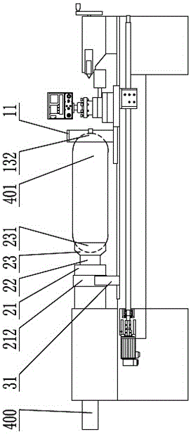
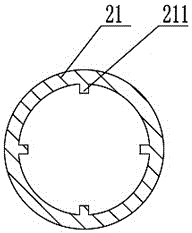
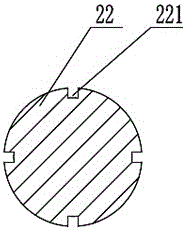
[0034] Such as Figure 1 to Figure 4 As shown, a fixture for turning high-pressure gas cylinders includes a rotating support, which includes a base 11, a support bearing 12 and a support body 13 disposed in the base 11, the support body 13 is connected to the inner ring of the support bearing 12, and the outer ring of the support bearing 12 is connected to the base 11. The above-mentioned fixture for turning the high-pressure gas cylinder also includes a telescopic chuck, which includes a cylinder 21, a telescopic The rod 22 and the claw 23, the claw 23 is connected to the front end of the telescopic rod 22, the telescopic rod 22 is arranged in the cylinder 21, and the cylinder 21 and the te...


PUM


Abstract

The invention provides a clamp for performing turning on a high pressure gas cylinder, and relates to the technical field of mechanical processing tools. The clamp comprises a rotating support and a telescopic chuck, wherein the rotating support comprises a base, a supporting bearing arranged in the base and a support body, the support body is connected with an inner ring of the supporting bearing, the outer ring of the supporting bearing is connected with the base, the telescopic chuck comprises a cylinder barrel, a telescopic rod and a claw, the claw is connected with the front end of the telescopic rod, the telescopic rod is arranged in the cylinder barrel, and rotating-prevention mechanisms matched with each other are arranged on the cylinder barrel and the telescopic rod. Large-scale reformation on a lathe is not needed when the clamp is used for performing turning on the high pressure gas cylinder, only the telescopic rod and the claw need to be pushed by a pushing device of the lathe, the weight of the telescopic rod and the claw is light, and the friction force between the telescopic rod and the cylinder barrel is small, so that the pushing device of the lathe can push the telescopic rod and the claw with a smaller push force, the clamp is small in abrasion during use, and the service life is long.

Description

technical field [0001] The invention relates to the technical field of machining tools, in particular to a fixture for turning high-pressure gas cylinders. Background technique [0002] The production process of high-pressure gas cylinders includes seamless steel pipe cutting and blanking, high-temperature bottle bottom collection, bottle bottom scraping, high-temperature bottle mouth closing, cylinder inner wall shot blasting, bottle mouth turning and other processes. [0003] In the actual production process, due to the large volume and special shape of the gas cylinder, the ordinary lathe cannot realize the turning process of the gas cylinder. The Chinese invention patent No. 01277981.4 discloses a lathe for turning the gas cylinder. The device pushes the sliding table, the spindle box and the chuck to move towards the support frame, so that the gas cylinder is clamped between the chuck and the support frame. Although the lathe has the function of turning the gas cylinder...

Claims


Application Information

Patent Timeline
Patent Type & Authority Patents(China)
IPC IPC(8): B23Q3/00
CPCB23B31/103B23Q1/76
Inventor 余卓
Owner 衡阳金化高压容器股份有限公司
Learn More