A Hovering Control Method Based on Parameter Optimization for Spacecraft Single-pulse Drop-shaped Flying Trajectory

A control method and spacecraft technology, applied in the direction of aerospace vehicle guidance devices, etc., can solve problems such as hovering time is not considered

Active Publication Date: 2016-04-27
HARBIN INST OF TECH
View PDF2 Cites 2 Cited by
  • Summary
  • Abstract
  • Description
  • Claims
  • Application Information

AI Technical Summary

Problems solved by technology

[0006] The purpose of the present invention is to propose a single-pulse drop-shaped hovering control method based on parameter optimization, to solve the problem that the control amount is continuous for the existing fixed-point hovering method; method to achieve hovering, without considering the fuel consumption of the tracking spacecraft hovering in the orbital plane of the target spacecraft due to the long hovering time

Method used


Image

  • A Hovering Control Method Based on Parameter Optimization for Spacecraft Single-pulse Drop-shaped Flying Trajectory
  • A Hovering Control Method Based on Parameter Optimization for Spacecraft Single-pulse Drop-shaped Flying Trajectory
  • A Hovering Control Method Based on Parameter Optimization for Spacecraft Single-pulse Drop-shaped Flying Trajectory

Examples


specific Embodiment approach 1

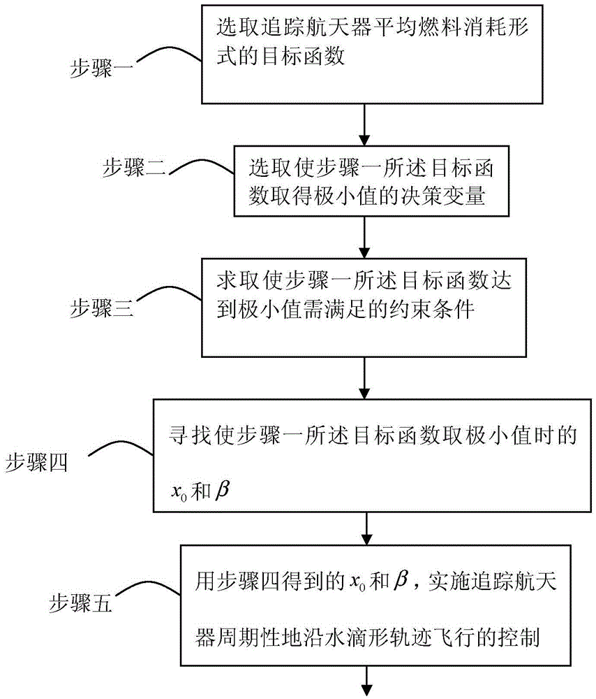
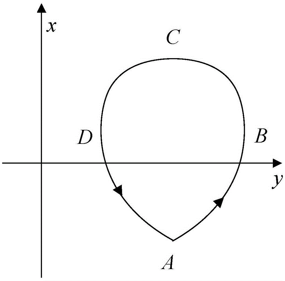
[0060] Specific implementation mode one: combine figure 1 , figure 2 , Figure 14 This embodiment will be described. A hovering control method based on parameter optimization of a spacecraft single-pulse drop-shaped flying trajectory described in this embodiment defines the coordinate system in the method as follows: in the relative coordinate system, that is, the orbital coordinate system s-xyz : The coordinate origin s is fixedly connected with the center of mass of the target spacecraft and moves along the orbit with it, the x-axis and the geocentric vector r of the target spacecraft s Coincidence, from the center of the earth to s, the y-axis is perpendicular to the x-axis in the orbital plane of the target spacecraft, and points to the direction of motion, the z-axis, the x-axis, and the y-axis form a right-handed coordinate system at right angles;

[0061] It is characterized in that the method comprises the following steps:

[0062] Step 1. In order to consider tra...

specific Embodiment approach 2

[0190] Specific embodiment two: the difference between this embodiment and specific embodiment one is: the concrete process of step 4 is:

[0191] keep picking different x 0 and β, using the nonlinear programming method, use the function fmincon in Matlab to track the x-direction component of the position of point A and the period T of tracking the spacecraft's drop-shaped orbital trajectory w The ratio β to the orbital period T of the target spacecraft is optimized to obtain the drop-shaped flying trajectory with the least fuel consumption required to track the hovering spacecraft. Other steps are the same as in the first embodiment.

[0192] Simulation

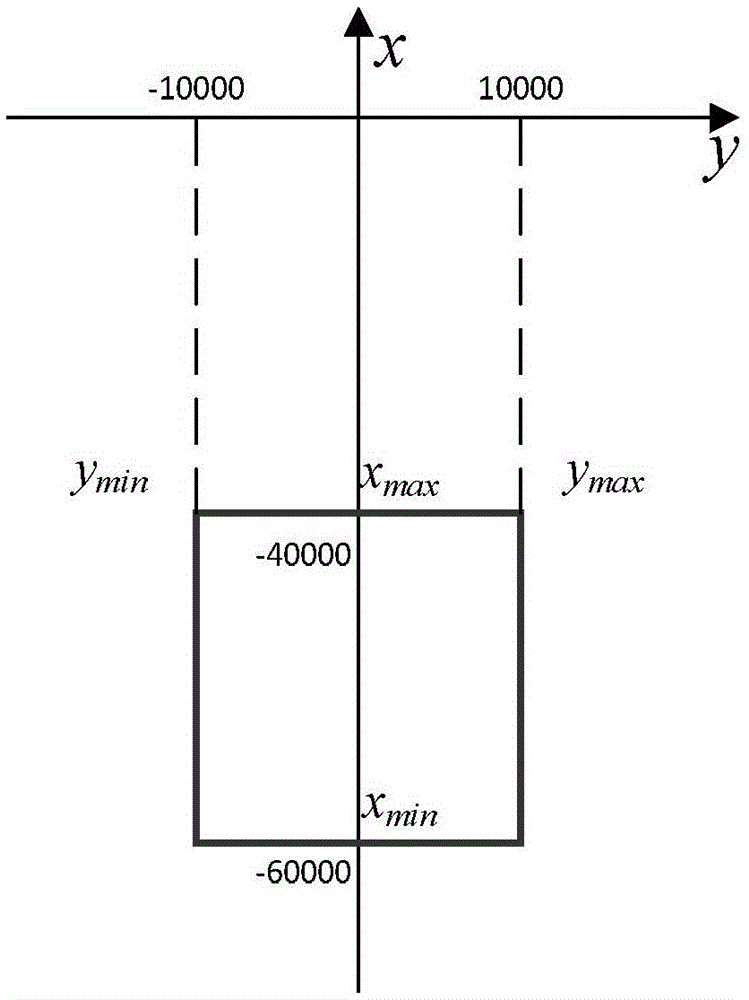
[0193] Assuming that the target spacecraft is in geostationary orbit (GEO), the hovering time is one orbital period, that is, 24 hours, [x min ,x max ,y min ,y max ]=[-60000,-40000,-10000,10000]m square hover position range as an example, such as image 3 shown.

[0194] choose y 0 =0, optimize the initial value to ...


PUM


Abstract

The invention discloses a parameter optimization-based spacecraft single-pulse drop-shaped fly-around track hover control method, belongs to the technical field of spacecraft track control, and aims to solve the problems that the existing fixed point hover method requires the control quantity to be continuous and the existing single-pulse drop-shaped fly-around method realizes hovering without considering the fuel consumption of a tracking spacecraft hovering on the track plane of a target spacecraft due to long hovering time. According to the technical scheme, the target spacecraft is positioned on a circular high-orbit track, the relative position range has upper and lower boundaries, the single-pulse drop-shaped fly-around track scheme with parameter optimization is adopted for implementation, and the scheme with the least performance index value, namely fuel consumption, is discovered on the basis that the entire drop-shaped track meets the position range requirement of hovering in consideration of the relative motion coordinate system based on a hill equation. The method is mainly used for track control of the spacecraft.

Description

technical field [0001] The invention relates to a short-distance relative orbital motion control method of a spacecraft, in particular to a hovering control method, and belongs to the technical field of spacecraft orbital control. Background technique [0002] An important research hotspot in today's aerospace field is the close-range relative orbital motion control of spacecraft. The relative orbital motion of a spacecraft is to study the continuous motion law of a spacecraft (tracking spacecraft) around another spacecraft (target spacecraft) . It is often applied to space missions such as formation flight, on-orbit maintenance, rendezvous and docking, tracking and monitoring. Currently the most commonly used forms of relative orbital motion are hovering (the relative position of the tracking spacecraft and the target spacecraft remains unchanged), accompanying flight (the tracking spacecraft flies around a point near the target spacecraft in a closed trajectory) and flyin...

Claims


Application Information

Patent Timeline
Patent Type & Authority Patents(China)
IPC IPC(8): B64G1/24
Inventor 孙延超凌惠祥李传江马广富刘昱晗李东禹
Owner HARBIN INST OF TECH
Why Eureka
Try Eureka