
System and method for controlling the fuel injection event in an internal combustion engine

Active Publication Date: 2010-02-25
GE GLOBAL SOURCING LLC
View PDF18 Cites 21 Cited by
  • Summary
  • Abstract
  • Description
  • Claims
  • Application Information

AI Technical Summary

Benefits of technology

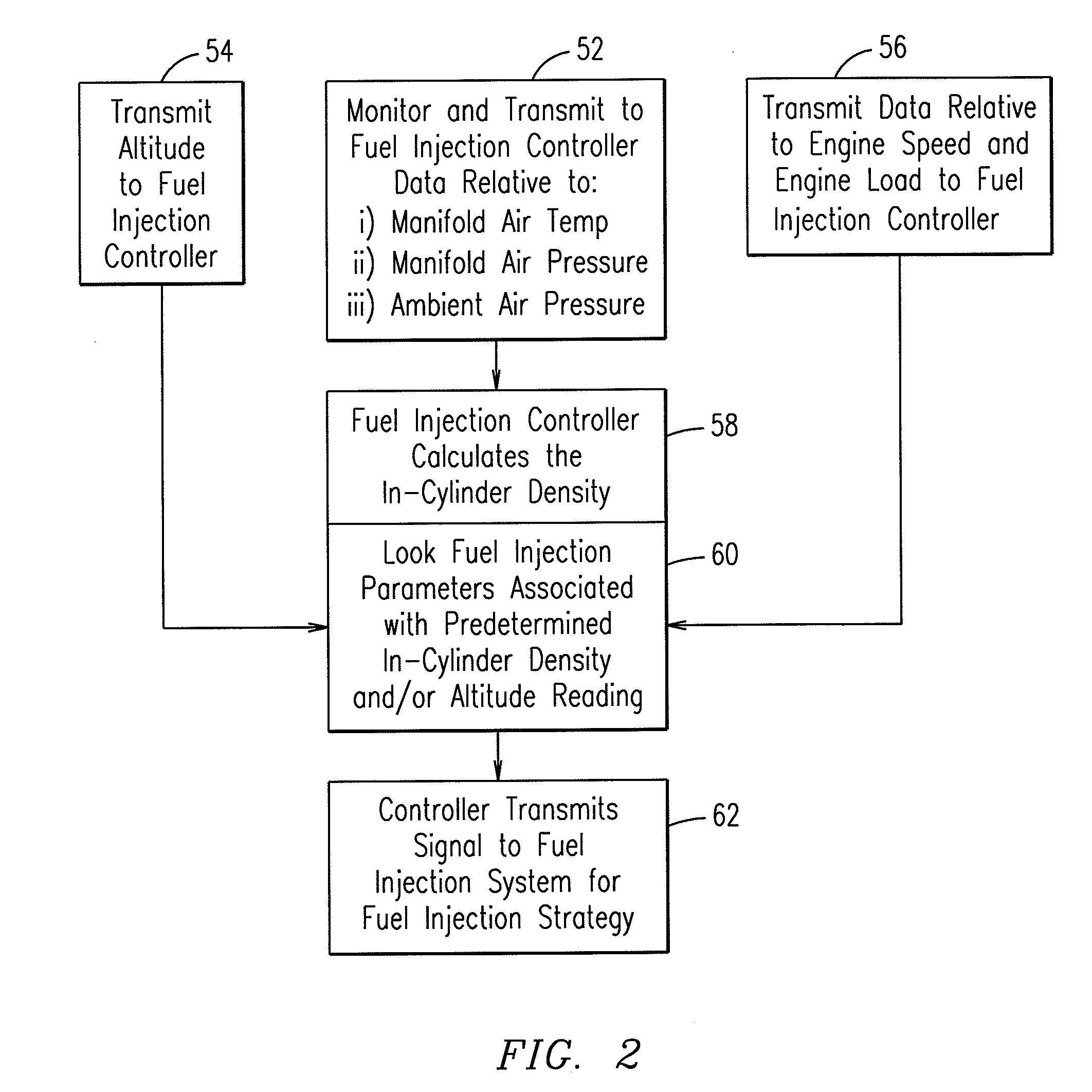
[0014]By calculating or estimating an in-cylinder gas density, a fuel system may consider or evaluate data that provides accurate information concerning what is taking place in the cylinder as compared to prior art systems that assumed that manifold air density is an accurate enough measurement to determine a fuel injection strategy. Combining this calculation with the flexibility of the common rail fuel injection timing and multiple injections leads to more efficient fuel consumption.

Problems solved by technology

Typically, the reduction of emissions, such as nitrous oxide, is accompanied by increased fuel consumption.
Accordingly, a fuel injection strategy that works well at lower altitudes may not be as desirable at high altitudes, because for example, the injection may result in emissions that fail to comply with appropriate regulations.
The hardware design of high-pressure unit pump fuel systems (also referred to as “unit pump systems”), for diesel internal combustion engines, limits the options available for selecting an effective strategy.
Moreover, the injection pressure is the same for each given notch and cannot be independently varied for different speeds or horsepower of the locomotive.
In addition, because pressure between injections must be revived, the current unit pump fuel systems used in locomotive diesel engines are limited to a single injection per injection cycle.
However, as noted above the unit pump systems are limited in that the injection pressure and the number of injections during an engine cycle are not variable.
In addition, the calculation of the air manifold density assumes that the condition of air manifold density is similar to a density of gas within the cylinder, which may not be accurate.

Method used


Image

  • System and method for controlling the fuel injection event in an internal combustion engine
  • System and method for controlling the fuel injection event in an internal combustion engine
  • System and method for controlling the fuel injection event in an internal combustion engine

Examples


Embodiment Construction

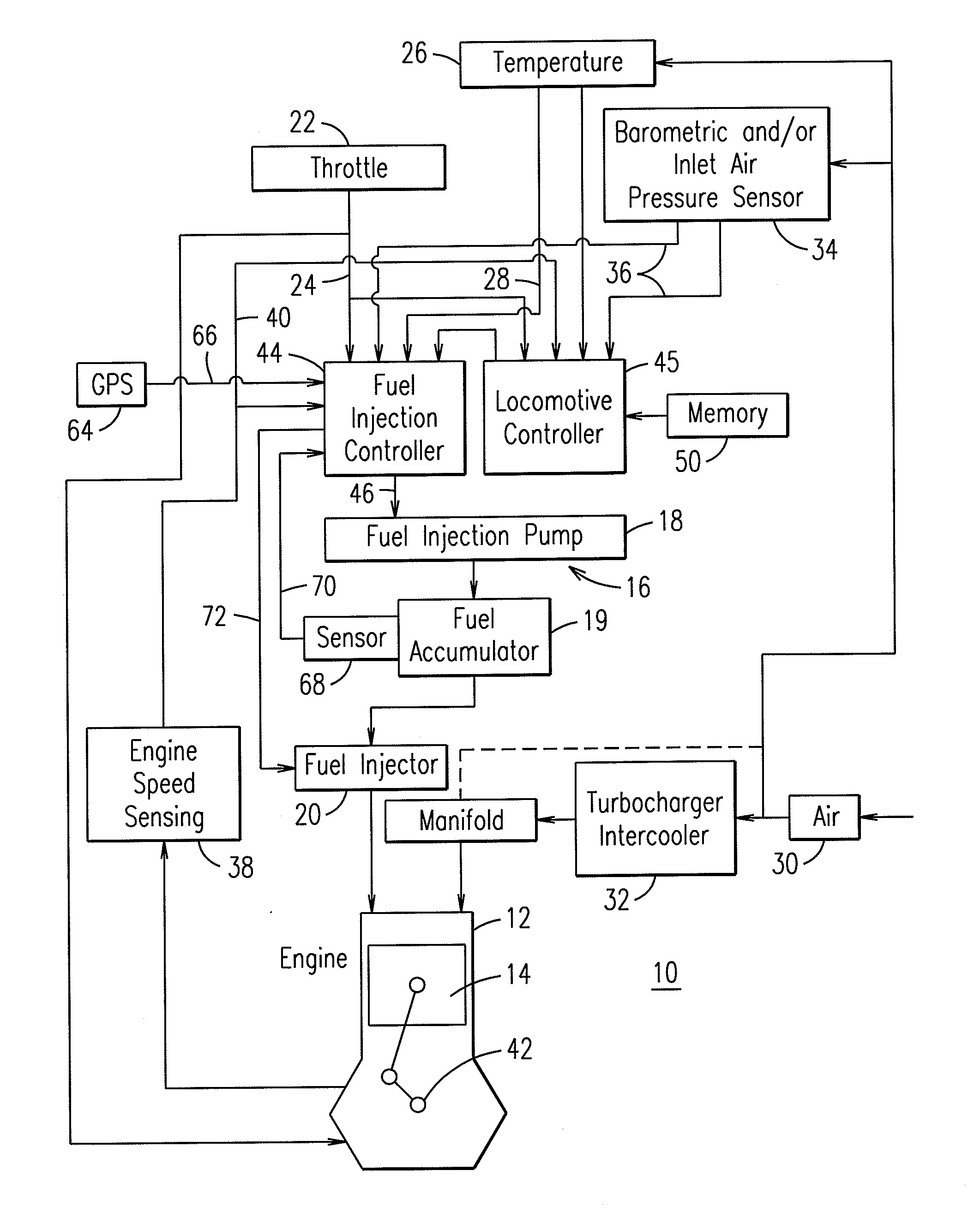
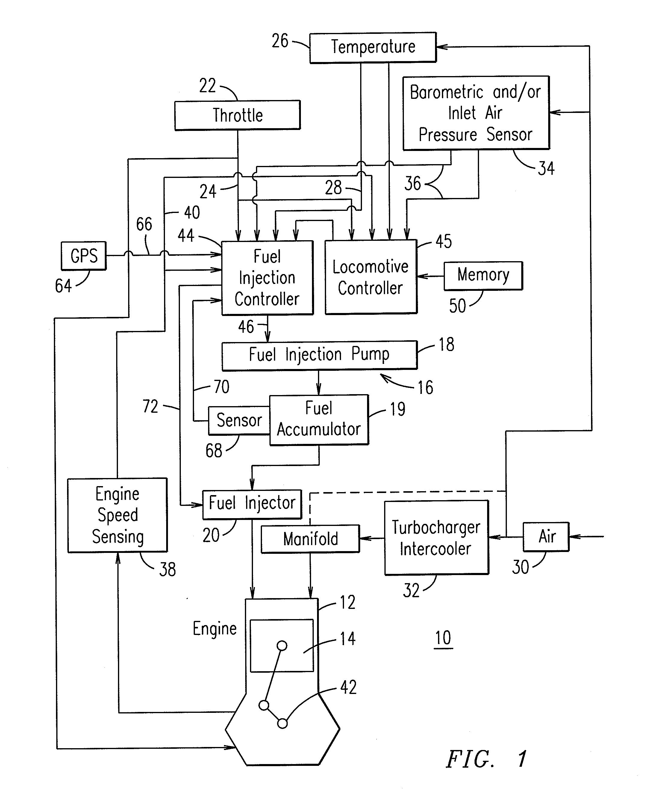
[0027]FIG. 1 is a schematic illustration of a diesel engine 10 using diesel or alternate liquid fuels and incorporating a fuel injection control scheme providing enhanced engine performance in varying environmental conditions. Engine 10 is representative of any large, medium-speed, multi-cylinder diesel engine such as may be used in locomotive, marine, or power generation applications. Engine 10 includes a plurality of power cylinders 12 (one illustrated) each having a piston 14 reciprocating therein. A fuel injection apparatus 16 injects fuel into the respective cylinders 12 in timed sequence with the reciprocation of the pistons 14. The fuel injection apparatus 16 may be of the common rail fuel system type, or other advanced high-pressure fuel system, and includes a fuel pump 18, a fuel accumulator 19 that stores fuel under pressure, and a fuel injector 20 associated with each cylinder 12. While the components 18, 19, and 20 are illustrated as separate parts these components may b...


PUM


Abstract

A controller, in electrical communication with the one or more of the injectors and a high-pressure fuel pump, generates a first signal responsive to which the valve in the injector opens or closes and a second signal responsive to which the high-pressure fuel pump increases or decreases the pressure level in the fuel accumulator. The system may also include one or more sensors to detect a pressure within the air manifold and to detect the pressure within the fuel accumulator. The controller is programmed to calculate an in-cylinder gas pressure. When the engine is operating at a maximum engine load and the in-cylinder gas pressure reaches or exceeds a maximum pressure limit, the controller transmits one or more signals to adjust the fuel injection timing and / or adjust the pressure in the fuel accumulator to maintain NOx and fuel consumption within acceptable limits.

Description

CROSS-REFERENCE TO RELATED APPLICATIONS[0001]This application claims priority to and is a Continuation-In-Part of U.S. application Ser. No. 11 / 858,345 filed Sep. 20, 2007, and incorporated herein by reference in its entirety.BACKGROUND OF THE INVENTION[0002]An embodiment of the invention disclosed herein relates generally to internal combustion engines. More specifically, the invention pertains to fuel injection systems and methods that control a fuel injection event in an internal combustion engine.[0003]Improving fuel efficiency while meeting emissions requirements is an ongoing effort in the design of internal combustion engines, including diesel engines. Typically, the reduction of emissions, such as nitrous oxide, is accompanied by increased fuel consumption. For locomotive engines in the United States, emissions compliance must be maintained over a wide range of altitudes and ambient temperatures. Accordingly, a fuel injection strategy that works well at lower altitudes may no...

Claims


Application Information

Patent Timeline
IPC IPC(8): F02M63/04F02M51/00
CPCF02D35/024F02D41/3845F02D41/40F02D2200/0402Y02T10/44F02D2200/0414F02D2200/0602F02D2200/703F02D2250/36F02D2200/0406Y02T10/40
Inventor GALLAGHER, SHAWN M.PRIMUS, ROYTAMMA, BHASKARTOPINKA, JENNIFERMISCHLER, ROBERTBODDU, RAJANI
Owner GE GLOBAL SOURCING LLC
Learn More