System and Method for Controlling the Fuel Injection Event in an Internal Combustion Engine

Active Publication Date: 2009-03-26
GE GLOBAL SOURCING LLC
View PDF31 Cites 23 Cited by
  • Summary
  • Abstract
  • Description
  • Claims
  • Application Information

AI Technical Summary

Benefits of technology

[0009]An embodiment for a high-pressure fuel injection system for controlling the fuel injection event in an internal combustion engine estimates an in-cylinder gas density and selecting a fuel injection strategy based on this estimation. The fuel injection system comprises a high-pressure fuel pump in fluid communication with a low pressure fuel reservoir, a high-pressure fuel accumulator, in fluid communication with the high-pressure fuel pump and one or more injectors that are in fluid communication with the fuel accumulator and each of the fuel injectors is in fluid communication with a corresponding cylinder in which a piston is supported. Each of the injectors has a valve that opens or closes responsive to electrical pulses.
[0010]A controller, in electrical communication with the one or more of the injectors and the high-pressure fuel pump, generates a first signal responsive to which the valve in the injector opens or closes and a second signal responsive to which the high-pressure fuel pump increases or decreases the pressure level in the high-pressure fuel accumulator. The system may also include one or more sensors for detecting a temperature of an air manifold, a pressure within the air manifold and a barometric pressure. The sensors generate data indicative of these parameters which data is sent to the controller. The controller is programmed to estimate an in-cylinder gas density using data received from the sensors. The controller is preferably in communication with a database having data re

Problems solved by technology

Typically, the reduction of emissions, such as nitrous oxide, is accompanied by increased fuel consumption.
Accordingly, a fuel injection strategy that works well at lower altitudes may not be as desirable at high altitudes, because for example, the injection may result in emissions that fail to comply with appropriate regulations.
The hardware design of high-pressure unit pump fuel systems (also referred to as “unit pump systems”), for diesel internal combustion engines, limits the options available for selecting an effective strategy.
Moreover, the injection pressure is the same for each given notch and can

Method used


Image

  • System and Method for Controlling the Fuel Injection Event in an Internal Combustion Engine
  • System and Method for Controlling the Fuel Injection Event in an Internal Combustion Engine
  • System and Method for Controlling the Fuel Injection Event in an Internal Combustion Engine

Examples


Embodiment Construction

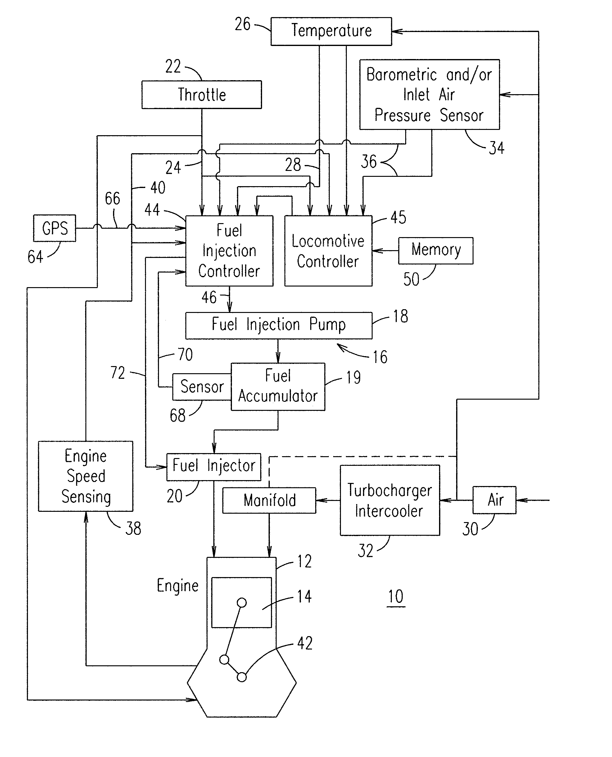
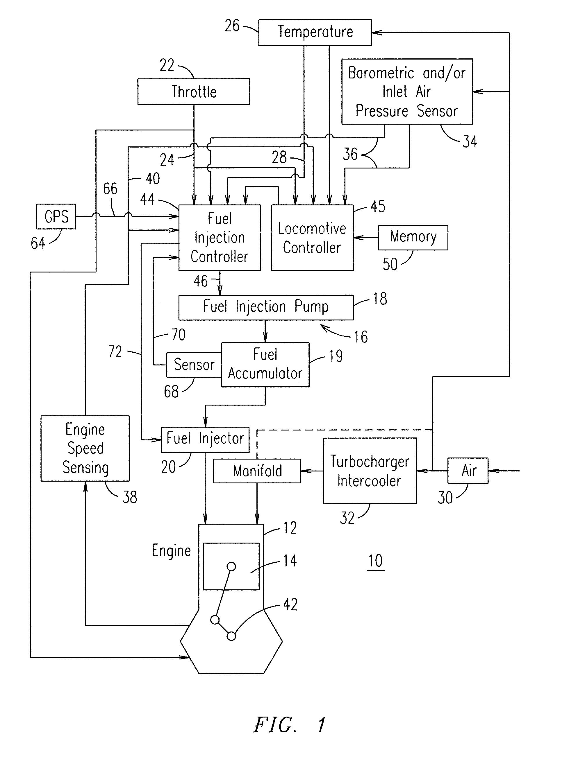
[0019]FIG. 1 is a schematic illustration of a diesel engine 10 using diesel or alternate liquid fuels and incorporating a fuel injection control scheme providing enhanced engine performance in varying environmental conditions. Engine 10 is representative of any large, medium-speed, multi-cylinder diesel engine such as may be used in locomotive, marine or power generation applications. Engine 10 includes a plurality of power cylinders 12 (one illustrated) each having a piston 14 reciprocating therein. A fuel injection apparatus 16 injects fuel into the respective cylinders 12 in timed sequence with the reciprocation of the pistons 14. The fuel injection apparatus 16 may be of the common rail fuel system type, or other advanced high-pressure fuel system, and includes a fuel pump 18, a fuel accumulator 19 that stores fuel under pressure and a fuel injector 20 associated with each cylinder 12. While the components 18, 19 and 20 are illustrated as separate parts these components may be i...


PUM


Abstract

A controller, in electrical communication with the one or more of the injectors and a high-pressure fuel pump, generates a first signal responsive to which the valve in the injector opens or closes and a second signal responsive to which the high-pressure fuel pump increases or decreases the pressure level in the fuel accumulator. The system may also include one or more sensors for detecting a temperature of air in an air manifold, a pressure within the air manifold and a barometric pressure. The controller is programmed to estimate an in-cylinder gas density using data received from the sensors. The controller accesses a database having data representative of one or predetermined in-cylinder gas densities that are associated with one or more predetermined fuel injection parameters. The controller then generates one or more commands indicative of the fuel injection parameters that are associated with a predetermined in-cylinder gas density.

Description

BACKGROUND OF THE INVENTION[0001]An embodiment of the invention disclosed herein relates generally to internal combustion engines. More specifically, the invention pertains to fuel injection systems and methods that control a fuel injection event in an internal combustion engine.[0002]Improving fuel efficiency while meeting emissions requirements is an ongoing effort in the design of internal combustion engines, including diesel engines. Typically, the reduction of emissions, such as nitrous oxide, is accompanied by increased fuel consumption. For locomotive engines in the United States, emissions compliance must be maintained over a wide range of altitudes and ambient temperatures. Accordingly, a fuel injection strategy that works well at lower altitudes may not be as desirable at high altitudes, because for example, the injection may result in emissions that fail to comply with appropriate regulations.[0003]Traditionally, operating parameters are changed in accordance with ambient...

Claims


Application Information

Patent Timeline
IPC IPC(8): F02M51/00
CPCF02D35/02F02D41/3845F02D41/40Y02T10/44F02D2200/0406F02D2200/0414F02D2200/703F02D2200/0402Y02T10/40
Inventor GALLAGHER, SHAWN MICHAELPRIMUS, ROYTAMMA, BHASKARTOPINKA, JENNIFER
Owner GE GLOBAL SOURCING LLC
Why Eureka
Try Eureka