
Illumination device for stimulating plant growth

a technology of plant growth and illumination device, which is applied in the direction of semiconductor devices for light sources, transportation and packaging, light and heating equipment, etc., can solve the problems of not every wavelength is efficient for crop growth, lamps have a limited lifespan, and need regular replacement, so as to reduce the requirements of heating systems, reduce the need for heating systems, and use the energy consumption of leds more efficiently

Active Publication Date: 2016-03-03
NHLDG
View PDF15 Cites 26 Cited by
  • Summary
  • Abstract
  • Description
  • Claims
  • Application Information

AI Technical Summary

Benefits of technology

The present invention is a system for stimulating plant growth using LEDs. The LEDs generate light with a desired spectral range, which can be designed to more efficiently use the heat generated by the LEDs. This not only reduces energy consumption but also results in a more turbulent microclimate and a more homogeneous environment for the plants, allowing for more efficient use of extra doses of carbon dioxide released in greenhouses to stimulate growth. Overall, this system is more cost-effective and efficient in promoting plant growth.

Problems solved by technology

However, not every wavelength is efficient for crop growth.
However, these lamps have a limited lifespan of typical 6 months to one year and therefore need regular replacement.
Further, these lamps consume a lot of energy, typically 600 W to 1000 W for approximately 10 square meters of crop.
Unfortunately, the energy to light conversion rate is quite low: only a few percent of the energy input is converted into usable light (photons), and the remaining energy is converted into heat and usually lost in the ridge of the greenhouse where it is of no use for crop.
This waste of energy (heat and energy consumption) is not acceptable anymore for economic, environmental and sustainability reasons.
Also the limited lifetime of gas discharge lamps puts an economic pressure on business, mainly, but not only, because of labour costs for replacement.

Method used


Image

  • Illumination device for stimulating plant growth
  • Illumination device for stimulating plant growth
  • Illumination device for stimulating plant growth

Examples


first embodiment

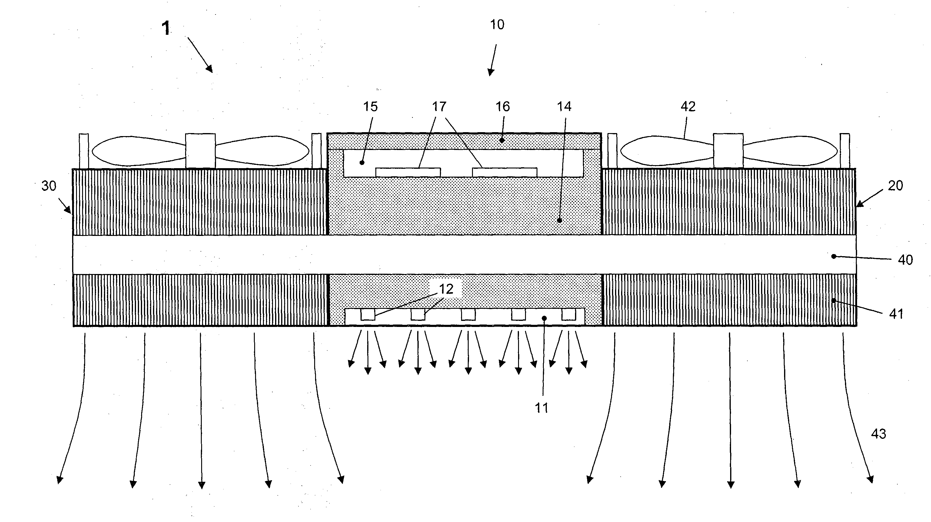
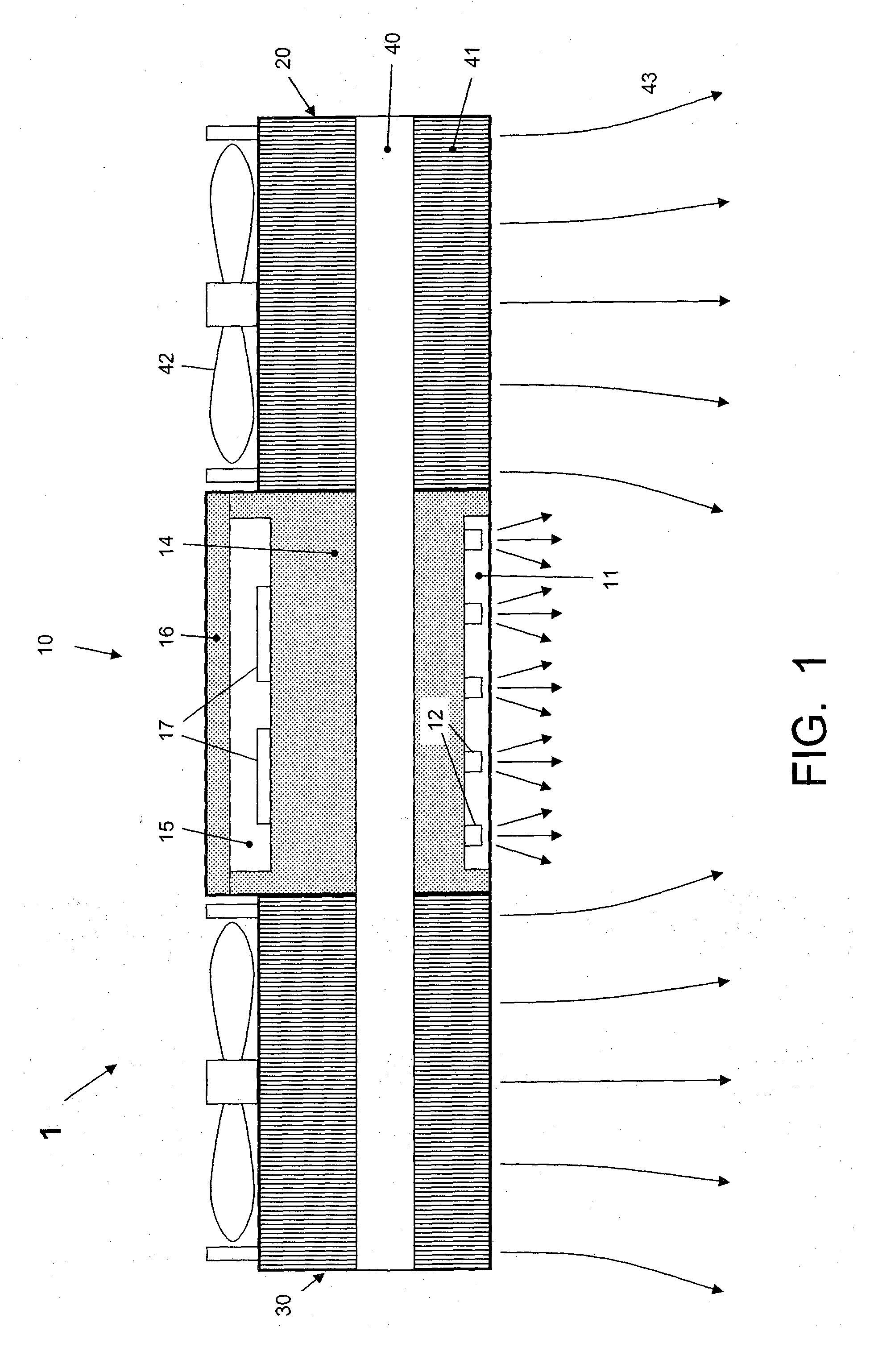
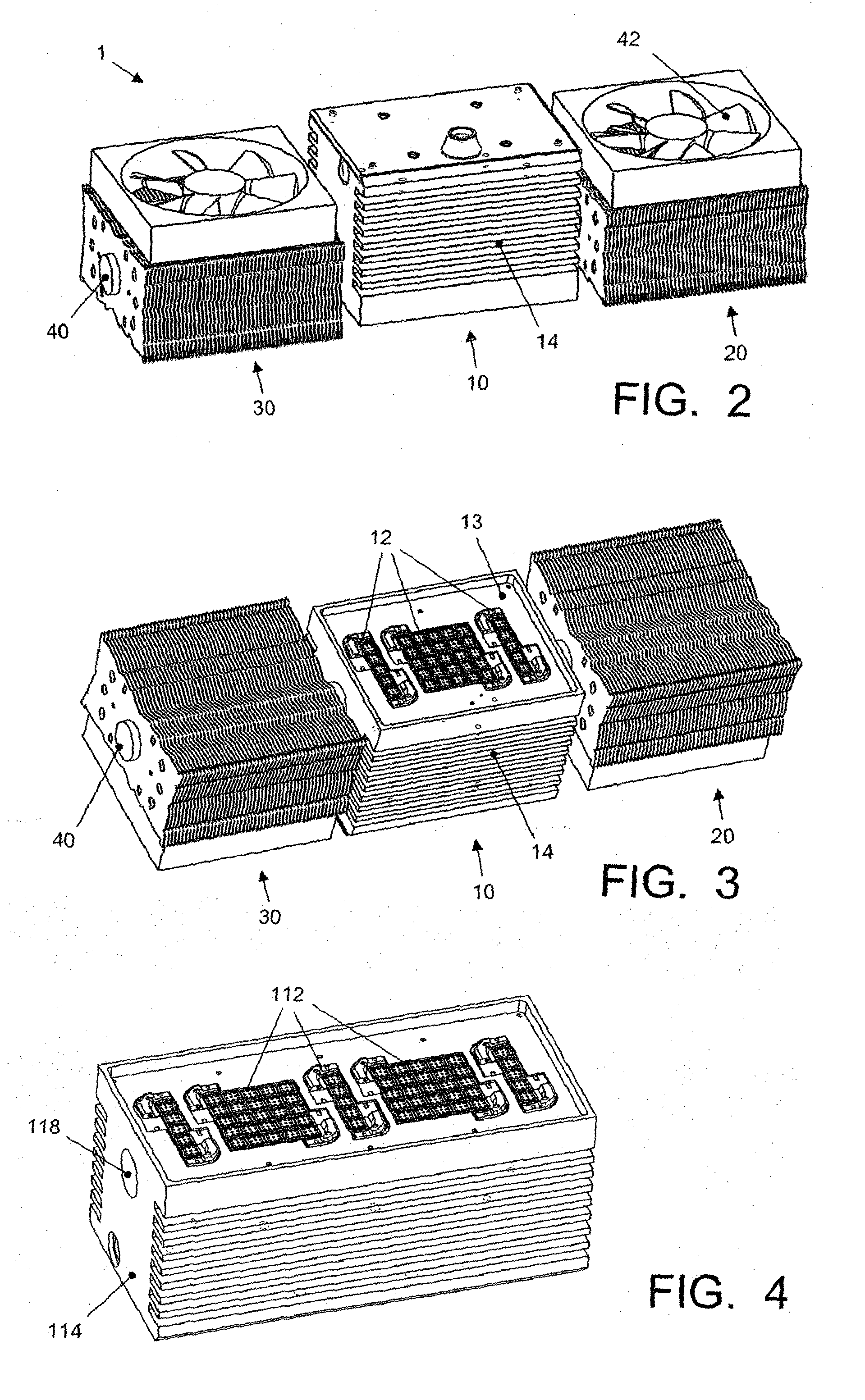
[0022]FIG. 1 schematically shows a compact and relatively low cost assimilation lamp device 1 according to the present invention. The lamp device 1 comprises a central lamp unit 10 which includes a body 14 of a general rectangular block shape. The lamp device 1 further comprises a plurality of LEDs 12 mounted to an under surface of the body 14, preferably in a recessed portion 11 thereof. At its upper side, the body 14 has a cabinet 15 accomodating driving and control circuitry 17 for the LEDs, suitably covered by a lid 16. The cabinet 15 will receive an electric supply cable for electrical supply, but this is not shown for sake of simplicity. The driving and control circuitry 17 generates driving current or the LEDs 12, which current is transported to the LEDs via conductors extending through the body 14, but this too is not shown for sake of simplicity.

[0023]The LEDs may be selected to emit light in (different) parts of the 300-700 nm spectrum. A 300W lamp version emits approximat...

second embodiment

[0039]To assure the downwards air stream 43, this second embodiment of the assimilation lamp 101 comprises a guiding hood 160 having a substantially inverse-U shaped profile with a top wall 161 and substantially vertical side walls 162. At its underside, the hood 160 is open. The top wall 161 has a raised portion 163 having a central opening 164, provided with a protective grating 165. Under the opening 164, surrounded and protected by the raised wall portion 163, the fan 42 is arranged. The top wall 161 lies in close proximity to the upper side of the fins or lamellae 41, so that in operation air is sucked in via the opening 164 and is forced to pass between the body 14 and the top wall 161 of the hood 160, following in X-direction the flow channels between the fins or lamellae 41. In this X-direction, the hood 160 is wider than the body 14, so that a collective flow path is defined between the side walls 162 and the body 14 where the air can do nothing else but flow down in vertic...


PUM


Abstract

An assimilation lamp device (1) for stimulating plant and crop growth comprises a central lamp unit (10), comprising a body (14) and a plurality of LEDs (12) mounted to an under surface of the body (14), wherein the body (14) is made of a thermally well conducting material, for instance aluminum, and acts as a heat sink for the heat generated by the LEDs. The body (14) is provided with cooling fins or lamellae (41). The assimilation lamp device further comprises air stream generating means (42) such as a fan for generating a downward air stream (43) in heat exchanging contact with the cooling fins or lamellae, so that heat is removed from the respective cooling block and used to increase the temperature of said downward air stream (43).

Description

FIELD OF THE INVENTION[0001]The present invention relates in general to the field of plant growth, specifically but not exclusively the field of large-scale commercially growing plants for production.BACKGROUND OF THE INVENTION[0002]In greenhouses, crop like tomatoes, cucumber, pepper, or more in general plants, are cultivated for an optimal yield. It is a general desire that crop grows as fast as possible in order to be able to harvest as early as possible and to obtain a commercial value as high as possible. Apart from nutrients, the most important growth factors are water, air (with a substantial percentage of carbon dioxide), temperature, and light, and a commercial plant grower will try to control these factors to some optimum values.SUMMARY OF THE INVENTION[0003]In modern greenhouses, artificial illumination as part of creating an optimal set of conditions for the stimulation of crop or ornamental plant growth is quite common. Especially when sun light is fading and / or periods...

Claims


Application Information

Patent Timeline
IPC IPC(8): A01G9/26A01G7/04F21V23/00F21V29/67F21V29/71F21V29/76
CPCA01G9/26F21V29/673F21V29/71F21Y2101/02A01G7/045F21V23/009F21V29/763F21Y2115/10A01G9/249Y02A40/25
Inventor SMITS, JOHANNES, JACOBUSVAN, VLIET, WILHELMUS, PETRUS
Owner NHLDG
Learn More