Hydraulic operating mechanism for high pressure switch and hydraulic working cylinder thereof

A technology of hydraulic operation and high-voltage switch, which is applied to high-voltage/high-current switches, power devices inside switches, electric switches, etc., and can solve problems such as increased cost and floor space, large hydraulic mechanism size, and large shock vibration. To achieve the effect of improving stability, rapid increase in motion speed, and increased acceleration

Active Publication Date: 2015-01-28
STATE GRID CORP OF CHINA +2
View PDF6 Cites 10 Cited by
  • Summary
  • Abstract
  • Description
  • Claims
  • Application Information

AI Technical Summary

Problems solved by technology

The opening speed required by the circuit breaker is the average speed within the specified time period or within the stroke period. In order to meet the requirements, when the acceleration and speed of the initial acceleration stage of the hydraulic cylinder are low, it can only be achieved by increasing the hydraulic pressure. The operating work of the mechanism is to increase the acceleration of the initial acceleration stage of the working cylinder. The specific measures are to increase the energy stored in the accumulator, the size of the hydraulic working cylinder, the hydraulic components and

Method used


Image

  • Hydraulic operating mechanism for high pressure switch and hydraulic working cylinder thereof
  • Hydraulic operating mechanism for high pressure switch and hydraulic working cylinder thereof
  • Hydraulic operating mechanism for high pressure switch and hydraulic working cylinder thereof

Examples


Embodiment Construction

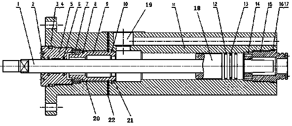
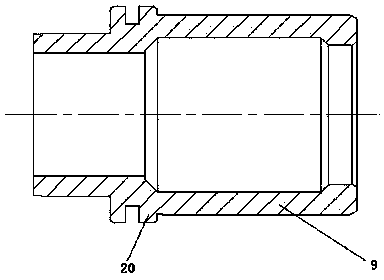
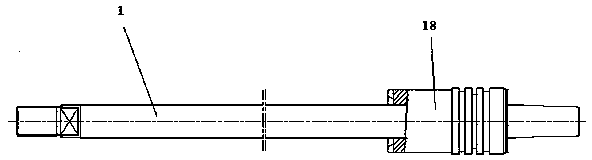
[0023] Embodiments of the hydraulic cylinder of the present invention are Figure 1-3As shown: the hydraulic working cylinder includes a cylinder body 11 with an inner chamber, a main piston 18 that is sealed and slidably fitted in the inner chamber of the cylinder body 11, and the inner chamber of the cylinder body 11 is separated by the main piston 18 to be on the left side of the main piston 18 The rod chamber on the right side of the main piston 18 and the rodless chamber on the right side of the main piston 18, the main piston 18 is fixed with the piston rod 1 extending in the left and right direction through the rod chamber, and the rod chamber of the cylinder body 11 along the An auxiliary piston 9 independent of the piston rod 1 is slidably mounted in the left and right directions.

[0024] The left end of the cylinder body 11 rod cavity is provided with a left nut 5 with an inner hole that is rotatably matched with the inner wall of the rod cavity. The left end of t...


PUM


Abstract

The invention relates to a hydraulic operating mechanism for a high pressure switch and a hydraulic working cylinder of the hydraulic operating mechanism. The hydraulic working cylinder comprises a cylinder body which is provided with an inner cavity and a main piston which is assembled into the inner cavity of the cylinder body in a sealing sliding mode; an auxiliary piston independent to the piston rod is assembled in a rod cavity of the cylinder body along the left direction and the right direction in a sliding mode; the area difference exists between the total area of a left-side pressure acting surface, which is leftward and acted by hydraulic oil, of the auxiliary piston and the total area of a right-side pressure acting surface, which is rightward and acted by the hydraulic oil, of the auxiliary piston, and a left limiting structure and a right limiting structure for stopping the auxiliary piston at a left limiting part and a right limiting part in the motion stroke of the auxiliary piston are arranged in the rod cavity corresponding to the motion stroke set by the auxiliary piston. The hydraulic working cylinder provided by the invention reduces the acceleration after the motion speed of the piston rod meets the requirement; the hydraulic operating mechanism using the hydraulic working cylinder is further provided.

Description

technical field [0001] The invention relates to a hydraulic operating mechanism for a high-voltage switch for operating a high-voltage switch to open and close. The hydraulic working cylinder of the invention is used in the hydraulic operating mechanism for a high-voltage switch. [0002] Background technique [0003] Ultra-high voltage and ultra-high voltage switches, such as circuit breakers and grounding switches, have high requirements for opening or closing speed due to their high voltage level and large breaking current (circuit breakers require high opening speed, and grounding switches require high closing speed). Brake speed is high), which requires its operating mechanism to provide greater operating power. At present, only the hydraulic mechanism can meet the operating power requirements of the ultra-high voltage and ultra-high voltage switches for opening and closing actions. What is widely used in the existing ultra-high voltage and ultra-high voltage switch...

Claims


Application Information

Patent Timeline
IPC IPC(8): F15B15/17F15B15/24F16J1/00F16J9/00H01H33/34H01H3/24
CPCF15B15/17F15B15/24F16J1/00F16J9/00H01H33/34F15B15/1409F15B15/1414F15B15/1447F15B15/1452H01H3/24
Inventor 顾根泉赵羡丽王亚辉陶平刘振华
Owner STATE GRID CORP OF CHINA
Why Eureka
Try Eureka