
A Target Tracking Method Based on Visual Tracking Technology

A target tracking and visual tracking technology, which is applied in the field of target tracking based on visual tracking technology, can solve the problems of increasing error rate, complicated operation, and easy mistakes, so as to reduce the error probability, simple and convenient operation, and improve accuracy. Effect

Active Publication Date: 2017-08-25
祁海江
View PDF2 Cites 0 Cited by
  • Summary
  • Abstract
  • Description
  • Claims
  • Application Information

AI Technical Summary

Problems solved by technology

[0002] At present, when selecting a target at a specific location in 3D space, auxiliary tools are often used to assist users in visual tracking in order to select a suitable target. However, the existing auxiliary tools have certain defects, which prevent users from quickly and accurately selecting the target. Goals are needed for the following reasons:
[0003] (1) Spatial sphere-assisted tracking: When the user uses spherical coordinates for target selection, due to the lack of a clear scale, the operator usually needs to continuously rotate or zoom in on the three-dimensional space object to find the target to be selected, which makes the operation more complicated , user tracking is also more difficult;
[0004] (2) Set the ruler on the screen, because the set ruler is far away from the content to be selected, it will cause the user's visual separation, so that the user is easy to make a wrong grid when selecting, which increases the error rate of selection
[0005] Due to the lack of 3D visual tracking tools in the prior art, the user often controls the 3D space target selection process manually through the operator, but due to the complicated operation, it is difficult to track human vision, so that the target selection is not enough Intuitive and visual, after setting the ruler on the screen, the distance between the ruler and the content will be far away, and visual separation will occur, and the probability of selection error will increase accordingly, thus affecting the precise positioning of the 3D space target

Method used


Image

  • A Target Tracking Method Based on Visual Tracking Technology
  • A Target Tracking Method Based on Visual Tracking Technology
  • A Target Tracking Method Based on Visual Tracking Technology

Examples


Embodiment 1

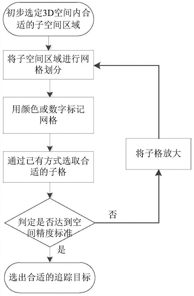
[0067] Depend on Figure 1-2 As shown, the present invention provides a target tracking method based on visual tracking technology, the method comprising:

[0068] Step A1: preliminarily select a suitable subspace area in 3D space, the selected subspace area is the subspace area directly selected by the user in 3D space according to the target to be selected;

[0069] Step A2: Divide the selected subspace area into grids according to the method of equal division or unequal division, such as 5×5×5 or 5×4×6;

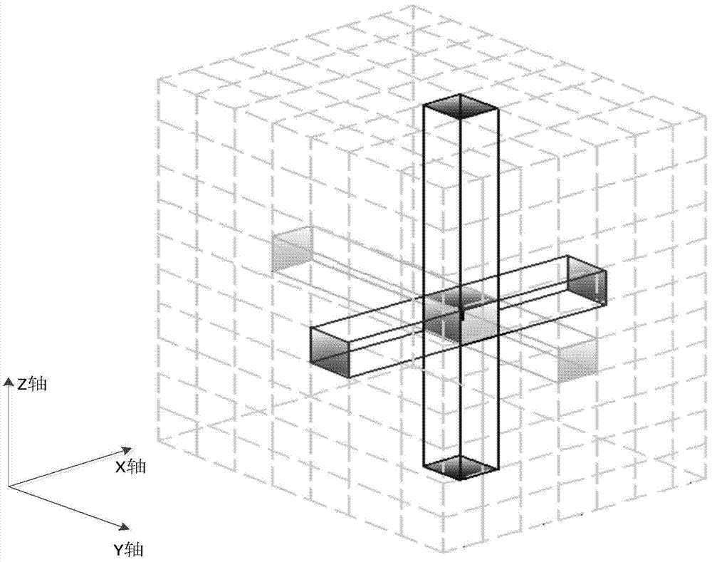
[0070] Step A3: Use color or number to mark the divided grid. The color mark is in the form of a gradient. The part where the grid intersects with the two planes of the selected subspace area has a darker color mark, and the part other than the intersection is colored The markers are lighter, where the X-axis marker-colored grid intersects the two planes of the selected subspace region in dark red, and the parts other than the intersection are light red, and the Y-axis ma...

Embodiment 2

[0075] Depend on Figure 1-4 As shown, the present invention provides a target tracking method based on visual tracking technology, the method comprising:

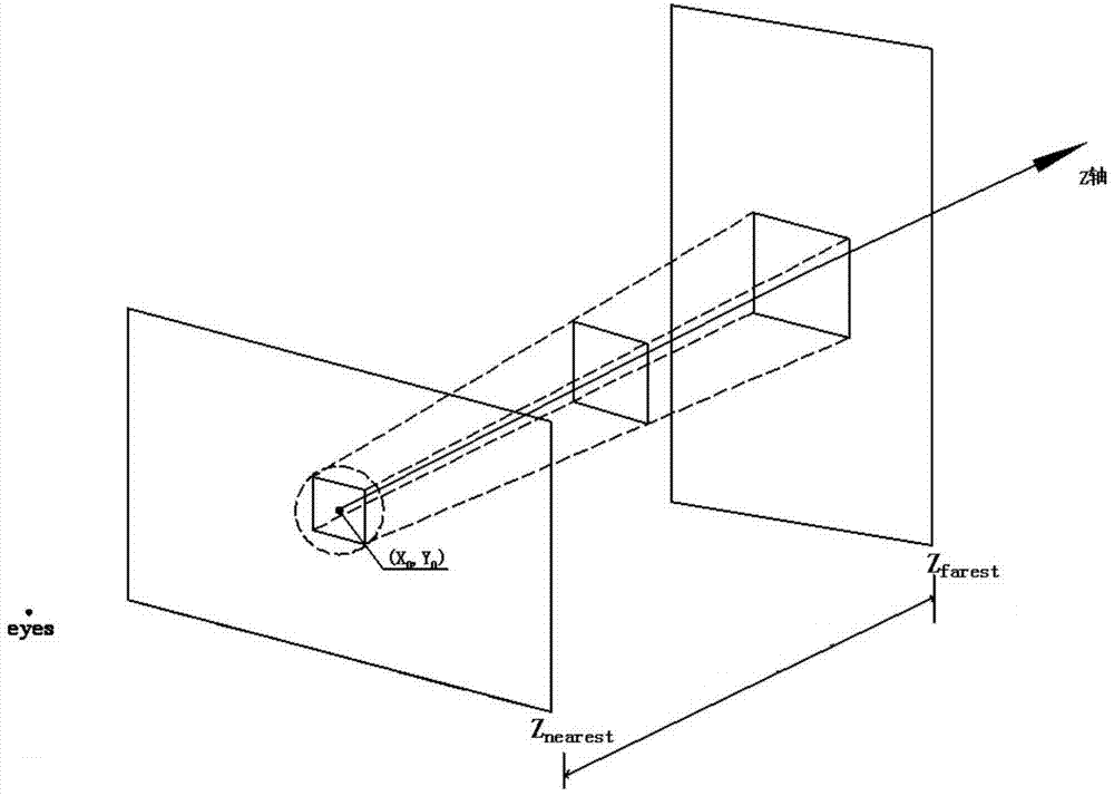
[0076] Step B1: In the 2D plane, the user selects a location point S 0 , record the plane coordinates of the location point (X 0 , Y 0 ), where X 0 Refers to the value of the user's position on the horizontal X-axis, Y 0 Refers to the value of the user's position in the vertical direction;

[0077] Step B2: Point S at the selected location 0 The front-end visual plane that delineates the 2D range for the center;

[0078] Step B3: Diffusion the front-end visible plane of the 2D range along the Z-axis direction according to the perspective relationship to form a 3D perspective column, and remove points outside the perspective column. The shape of the diffusion is circular or square, and the user can follow the simple , The principle of convenience Choose the spreading shape by yourself, in order to facilitate the obse...

Embodiment 3

[0089] Depend on Figure 1-6 As shown, the present invention provides a target tracking method based on visual tracking technology, the method comprising:

[0090] Step C1: In the 2D plane, the user selects a location point S 0 , record the plane coordinates of the location point (X 0 , Y 0 );

[0091] Step C2: Point S at the selected location 0 The front-end visual plane that delineates the 2D range for the center;

[0092] Step C3: Spread the front-end visible plane of the 2D range along the Z-axis direction according to the perspective relationship to form a 3D perspective column, and remove points outside the perspective column;

[0093] Step C4: grouping the candidate points on the 3D perspective column;

[0094] The method of grouping can adopt the adjacent distance threshold judgment method or the K-means grouping method;

[0095] The adjacent distance threshold judgment method comprises the following steps:

[0096] Set the threshold of a depth interval distanc...


PUM


Abstract

The invention provides a target tracking method based on a novel visual tracking technology. According to the method, a three-dimensional space area is latticed, and is marked with colors or numbers, sublattices to be selected are obtained by moving lattices, the selected sublattices are amplified step by step for visual aids, lattice generation and selection are carried out repeatedly until the set space precision standard is achieved, and finally a target to be selected by a user is determined. According to the method, users of different industries can track targets more visually and vividly according to industry needs or the needs of themselves, target tracking visualization is achieved, the target tracking operation action and state are closely combined, operation is easier and more convenient, the error probability is greatly reduced, and therefore target tracking accuracy is further improved.

Description

technical field [0001] The invention relates to the fields of computer vision and computer graphics, in particular to an object tracking method based on visual tracking technology for object tracking in 3D space. Background technique [0002] At present, when selecting a target at a specific location in 3D space, auxiliary tools are often used to assist users in visual tracking in order to select a suitable target. However, the existing auxiliary tools have certain defects, which prevent users from quickly and accurately selecting the target. Goals are needed for the following reasons: [0003] (1) Spatial sphere-assisted tracking: When the user uses spherical coordinates for target selection, due to the lack of a clear scale, the operator usually needs to continuously rotate or zoom in on the three-dimensional space object to find the target to be selected, which makes the operation more complicated , user tracking is also more difficult; [0004] (2) setting a scale on t...

Claims


Application Information

Patent Timeline
Patent Type & Authority Patents(China)
IPC IPC(8): G06T7/20G06T17/00
CPCG06T3/40G06T3/604G06T7/593G06T2207/20108
Inventor 祁海江
Owner 祁海江
Learn More