Anti-theft system and method

A technology of anti-theft system and anti-theft method, which is applied in the direction of anti-theft alarms, instruments, alarms, etc., can solve the problem of high cost, achieve low installation cost, good anti-theft effect, and save labor costs

Inactive Publication Date: 2015-01-28
SHANGHAI SIMCOM LTD
View PDF6 Cites 6 Cited by
  • Summary
  • Abstract
  • Description
  • Claims
  • Application Information

AI Technical Summary

Problems solved by technology

[0003] The technical problem to be solved by the present invention is to overcome the disadvantages of the prior art that special personnel are required to observe and the cost is high when using a camera for monitoring, and to provide a low-cost anti-theft system and method that does not require real-time observation by personnel

Method used


Image

  • Anti-theft system and method
  • Anti-theft system and method
  • Anti-theft system and method

Examples


Embodiment 1

[0045] An anti-theft system used to prevent strangers from entering the room through the door to steal. The monitoring area of ​​the anti-theft system mainly includes the door and the area around the door with a radius of about 1-2 meters.

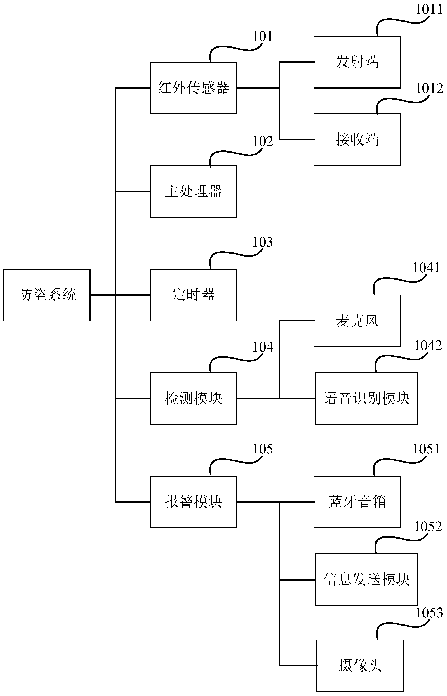
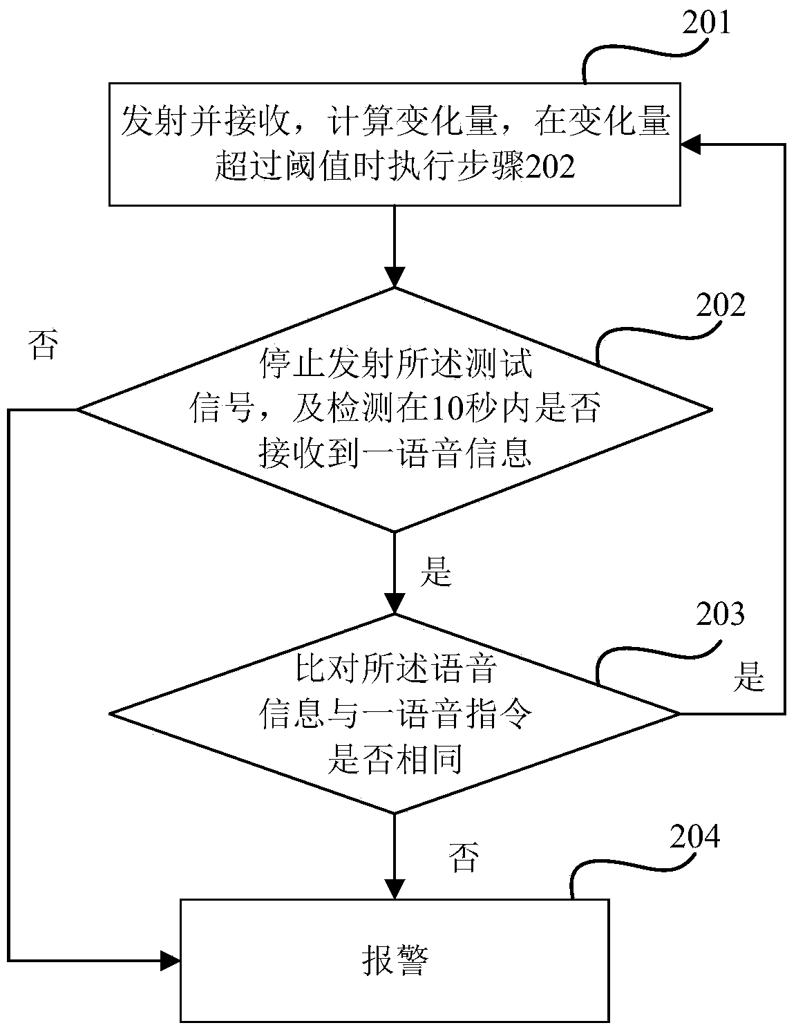
[0046] see figure 1 , the anti-theft system includes an infrared sensor 101, a main processor 102, a timer 103, a detection module 104 and an alarm module 105. The prescribed time set by the timer 103 is 10 seconds.

[0047] The infrared sensor 101 includes a transmitting end 1011 and a receiving end 1012, and the transmitting end 1011 and the receiving end 1012 are arranged on the door frame on the same side of the door. The transmitting end 1011 is used for transmitting a test signal every 2 seconds, and the receiving end 1012 is used for receiving the feedback signal after the test signal is reflected by the gate. The receiving end 1012 is also used for sending the feedback signal to the main processor 102 .

[0048]The main process...

Embodiment 2

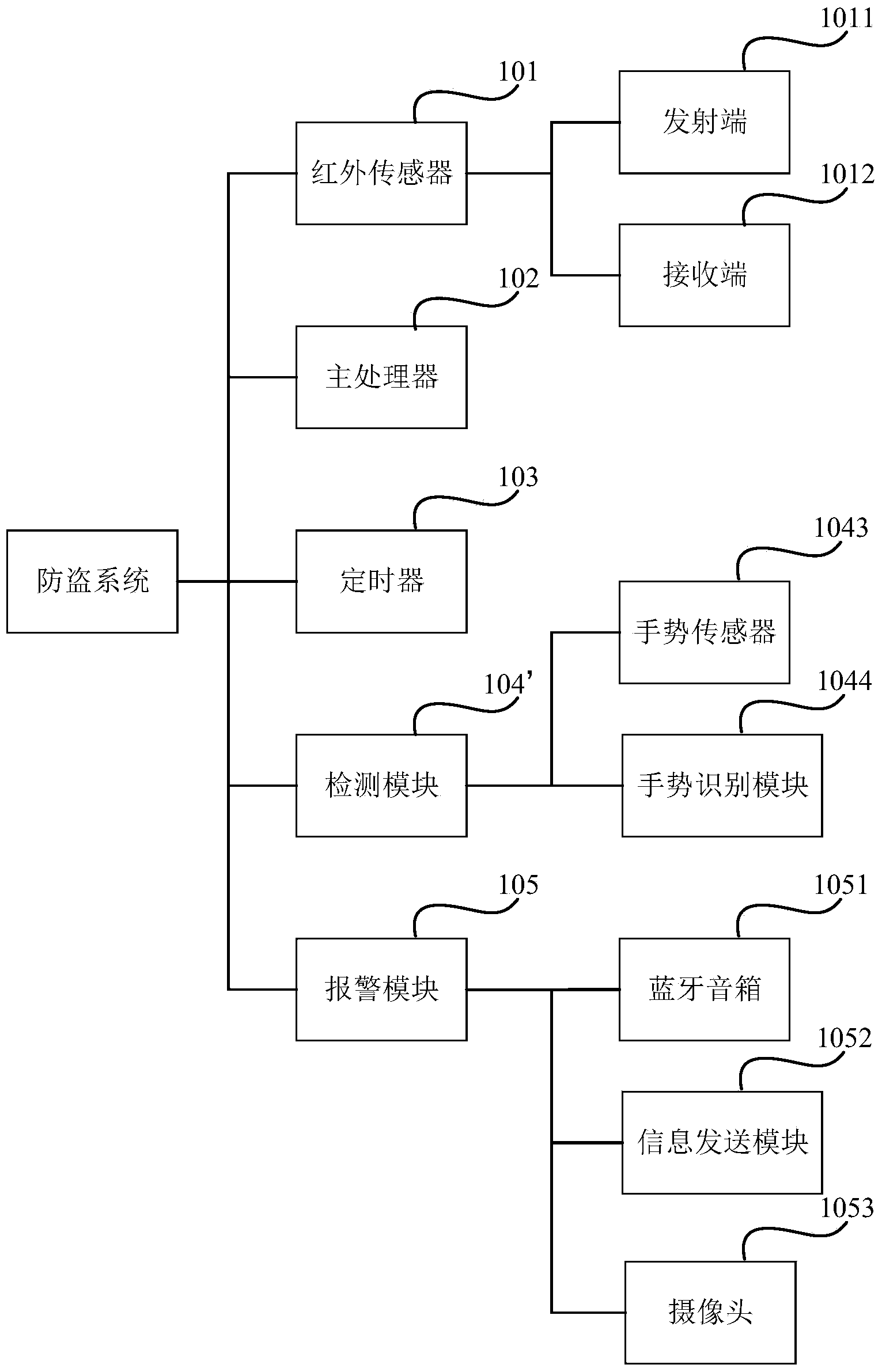
[0062] The alarm system of this embodiment is basically the same as the alarm system of Embodiment 1, except that, referring to 3, the detection module 104' of the alarm system of this embodiment includes a gesture sensor 1043 and a gesture recognition module 1044. The detection module 104' is configured to use the gesture recognition module 1044 to compare whether the gesture information is the same as a gesture instruction when it detects that the gesture information input by the gesture sensor 1043 is received within 10 seconds, and if so, Start the infrared sensor 101 and the main processor 102, if not, call the alarm module 105 to alarm. The gesture command is pre-stored in the detection module 104', which is equivalent to an early warning release signal.

[0063] The gesture sensor 1043 and the gesture recognition module 1044 can be integrated into the same sensing device, and optional models include GP2AP052A00F and the like.

[0064] The alarm method of this embodimen...

Embodiment 3

[0067] The alarm system of the present embodiment is basically the same as the alarm system of embodiment 1, the difference is that, see Figure 5 The detection module 104 ″ of the alarm system in this embodiment includes a microphone 1041 , a voice recognition module 1042 , a gesture sensor 1043 and a gesture recognition module 1044 .

[0068] The detection module 104" is used to use the voice recognition module 1042 to compare whether the voice information is the same as a voice command when it detects that the voice information input through the microphone 1041 is received within 10 seconds, and is also used to When it is detected that the gesture information input by the gesture sensor 1043 is received within 10 seconds, the gesture recognition module 1044 is used to compare whether the gesture information is the same as a gesture instruction, and if the two comparisons are the same, start the Described infrared sensor 101 and described main processor 102, otherwise, call ...


PUM


Abstract

The invention discloses an anti-theft system which comprises a sensor, a main processor, a timer, a detection module and an alarm module. The sensor is used for regularly sending testing signals, receiving feedback signals of the testing signals after the testing signals are reflected by a monitoring area, and transmitting the feedback signals to the main processor. The main processor is used for calculating the variable quantity of the feedback signals which are received at the latest two times, and simultaneously starting the timer and the detection module and stopping the sensor when the variable quantity exceeds a threshold value. The detection module is used for detecting whether an all-clear signal is received within a specified time period set by the timer, if yes, the sensor and the main processor are started, and if not, the alarm module is called for giving out an alarm. The anti-theft system overcomes the defects that when a camera is used for monitoring, specialized personnel need to watch and the cost is high in the prior art, and has the advantages of being low in installing cost, high in monitoring accuracy, capable of giving out the alarm timely and the like.

Description

technical field [0001] The invention relates to an anti-theft system and method. Background technique [0002] Common anti-theft systems use cameras for monitoring. The use of camera monitoring not only requires special personnel to observe in order to find out whether there is a theft in real time, but also needs to install cameras in multiple places, which has high equipment costs and installation costs. . Contents of the invention [0003] The technical problem to be solved by the present invention is to overcome the disadvantages in the prior art that special personnel are required to observe and the cost is high when using a camera for monitoring, and to provide a low-cost anti-theft system and method that does not require real-time observation by personnel. [0004] The present invention solves the above technical problems through the following technical solutions: [0005] The invention provides an anti-theft system, which is characterized in that it includes a se...

Claims


Application Information

Patent Timeline
IPC IPC(8): G08B13/00
CPCG08B13/181
Inventor 彭浩强
Owner SHANGHAI SIMCOM LTD
Why Eureka
Try Eureka