Insulation device

A technology of insulating devices and shells, which is applied to high-voltage air circuit breakers, electrical components, electric switches, etc., can solve problems such as large volume, and achieve the effect of solving excessive volume

Active Publication Date: 2015-01-28
BEIJING SOJO ELECTRIC
View PDF9 Cites 1 Cited by
  • Summary
  • Abstract
  • Description
  • Claims
  • Application Information

AI Technical Summary

Problems solved by technology

[0005] The main purpose of the present invention is to provide an insulating device to solve the problem that the insulating device in the prior art is too large for the use of the insulating knife.

Method used


Image

  • Insulation device
  • Insulation device
  • Insulation device

Examples


Embodiment Construction

[0025] It should be noted that, in the case of no conflict, the embodiments in the present application and the features in the embodiments can be combined with each other. The present invention will be described in detail below with reference to the accompanying drawings and examples.

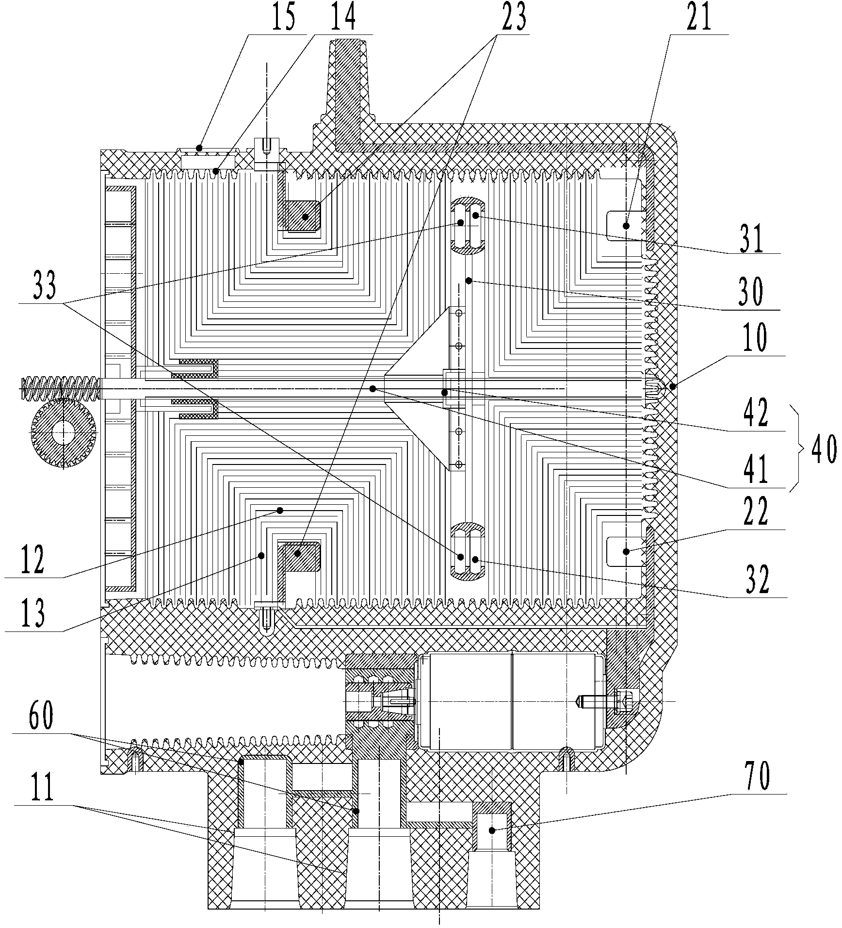
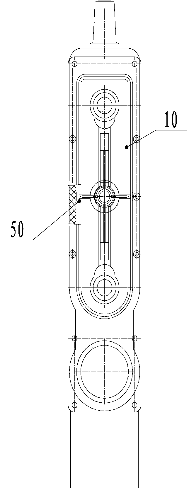
[0026] Such as figure 1 and figure 2 As shown, the insulating device of this embodiment includes: a housing 10, a conductive element and a switch mechanism. Wherein, the conductive element is disposed in the housing 10, and the conductive element includes a contact. The contacts include an incoming line contact 21 and an outgoing line contact 22, and the incoming line contact 21 and the outgoing line contact 22 are electrically connected through a switch mechanism. The switch mechanism includes: a conductive rod 30 is movably arranged in the housing 10 along a linear direction, and the conductive rod 30 includes a first position for connecting the incoming line contact 21 and the outgoing l...


PUM


Abstract

The invention provides an insulation device which comprises a shell (10) and an electric conducting element arranged in the shell (10). The electric conducting element comprises contacts which comprise a wire inlet contact (21) and a wire outlet contact (22), the wire inlet contact (21) and the wire outlet contact (22) are electrically connected through a switch mechanism which comprises a conducting rod (30) and a power piece (40), the conducting rod (30) is arranged in the shell (10) and can move in the linear direction, the conducting rod (30) comprises a first position where the wire inlet contact (21) and the wire outlet contact (22) are communicated and a second position where electric connection of the wire inlet contact (21) and the wire outlet contact (22) is interrupted, and the power piece (40) drives the conducting rod (30) to move in the linear direction. By means of the technical scheme, the problem that in the prior art, an insulation device is too large in size in order to meet the use requirement of an insulation knife is effectively solved.

Description

technical field [0001] The invention relates to the technical field of switches, in particular to an insulating device. Background technique [0002] The existing widely used insulated fully sealed switchgear generally includes an isolation part, a load switch part, and an inlet and outlet bushing part. Among them, most of the isolation is knife-type, including static contacts and isolation knives. Each time the switch is opened or closed, the isolation knife needs to be rotated to separate or contact the isolation knife with the static contact. [0003] The above isolation part has high requirements on the degree of contact between the isolation blade and the contact, and the degree of contact between the isolation blade and the contact is related to the temperature rise and dynamic and thermal stability of the entire device. Especially as the voltage level increases, a great pressure is needed to ensure that the isolation knife is in full contact with the contact. [00...

Claims


Application Information

Patent Timeline
Patent Type & Authority Applications(China)
IPC IPC(8): H01H33/53
CPCH01H33/42H01H33/53
Inventor 唐晓鹏王文焦孙龙韩雪莲周彦昭李宗旺
Owner BEIJING SOJO ELECTRIC
Why Eureka
Try Eureka