Laser light source device and projection equipment

A laser light source and laser technology, applied in projection devices, optics, optical components, etc., can solve the problems of long laser light path and large volume of the laser light source device, and achieve the effect of reducing the volume

Pending Publication Date: 2022-07-01
QINGDAO HISENSE LASER DISPLAY CO LTD
View PDF0 Cites 0 Cited by
  • Summary
  • Abstract
  • Description
  • Claims
  • Application Information

AI Technical Summary

Problems solved by technology

[0004] However, the path of the laser light path in the above-mentioned laser light sourc

Method used


Image

  • Laser light source device and projection equipment
  • Laser light source device and projection equipment
  • Laser light source device and projection equipment

Examples


Embodiment Construction

[0028] In order to make the objectives, technical solutions and advantages of the present application clearer, the embodiments of the present application will be further described in detail below with reference to the accompanying drawings.

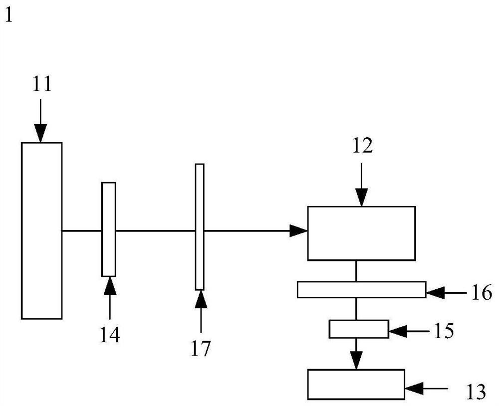
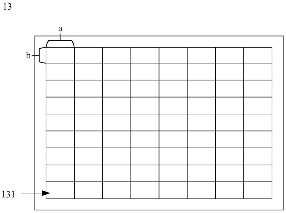
[0029] figure 1 is a schematic structural diagram of a laser light source device provided in the embodiment of the present application, such as figure 1 As shown, the laser light source device 1 includes a laser array 11 , a light conducting component 12 and a fly-eye lens 13 arranged in sequence along the optical path direction. The fly-eye lens 13 includes a plurality of rectangular lenses arranged in an array. The laser array 11 emits light beams, and the light guide assembly 12 is used for receiving the light beams emitted by the laser array 11 and guiding the light beams to the fly-eye lens 13 .

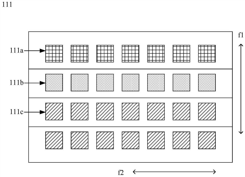
[0030] The laser array 11 includes a plurality of lasers arranged in an array, the fast axis direction of the laser is parallel to the sh...


PUM


Abstract

The invention discloses a laser light source device, and belongs to the field of laser display. The laser light source device comprises a laser array, a light conduction assembly and a fly's-eye lens, the fly's-eye lens comprises a plurality of rectangular lenses arranged in an array, the fast axis direction of the laser is parallel to the short sides of the rectangular lenses in the fly's-eye lens, and the slow axis direction of the laser is parallel to the long sides of the rectangular lenses in the fly's-eye lens. The sine value of the divergence angle of the fast axis of the laser is larger than the sine value of the aperture angle of the long side of the rectangular lens, and the sine value of the divergence angle of the slow axis of the laser is larger than the sine value of the aperture angle of the short side of the rectangular lens. Parameters of the laser and the fly's-eye lens are associated, the dodging function can be conveniently achieved through the fly's-eye lens, compared with a light guide pipe, the fly's-eye lens is small in size in the light path direction, and the size of the laser light source device is also small. The problem that the size of the laser light source device is too large in the prior art is solved, and the effect of reducing the size of the laser light source device is achieved.

Description

technical field [0001] The present application relates to the field of laser display, in particular to a laser light source device and projection equipment. Background technique [0002] With the continuous pursuit of picture color, laser projection with the advantages of large imaging picture, high spectral brightness and wide color gamut has been developed. Among them, three-color semiconductor lasers have been used in laser projection technology as laser light sources. [0003] At present, a laser light source device includes a laser array, a light-conducting component and a light-pipe which are arranged in sequence along an optical path. The laser array emits green, blue and red light. The three-color light is combined by the light-conducting component, and then homogenized through the light guide. The homogenized laser is emitted from one end of the light guide. [0004] However, in the above-mentioned laser light source device, the path of the laser light path is rel...

Claims


Application Information

Patent Timeline
IPC IPC(8): G03B21/20G02B3/00G02B27/14
CPCG03B21/2033G03B21/208G02B3/0037G02B3/0056G03B21/2066G02B27/141G03B21/206G02B19/0014G02B19/0057G02B3/0062G02B27/48G02B27/0961G03B21/2006G03B21/008G02B5/3025G02B13/06G02B27/102G02B27/30G03B21/2013
Inventor 李巍田有良唐甜甜
Owner QINGDAO HISENSE LASER DISPLAY CO LTD
Why Eureka
Try Eureka