
Grass feeding mechanism of a combine harvester

A combine harvester and grass feeding technology, applied in the direction of harvesters, agricultural machinery and implements, cutters, etc., can solve the problems of grain leakage, loose or worn joints between headers and conveying troughs, etc., to prevent grain leakage and prevent The problem of secondary leakage and the effect of prolonging the service life

Active Publication Date: 2016-05-04
宿迁诺泽建设工程有限公司
View PDF5 Cites 0 Cited by
  • Summary
  • Abstract
  • Description
  • Claims
  • Application Information

AI Technical Summary

Problems solved by technology

[0002] The grass feeding mechanism of the combine harvester includes the header and the conveying trough, but there is often a problem of grain leakage between the grass inlet of the existing conveying trough and the grass outlet of the cutting platform, and the cutting platform needs to be raised or lowered in real time during the working process. , the conveying trough is also required to be raised and lowered together with the header, and after long-term use, there will be looseness or wear at the joint between the header and the conveying trough

Method used


Image

  • Grass feeding mechanism of a combine harvester
  • Grass feeding mechanism of a combine harvester
  • Grass feeding mechanism of a combine harvester

Examples


Embodiment Construction

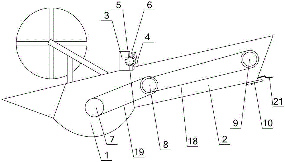
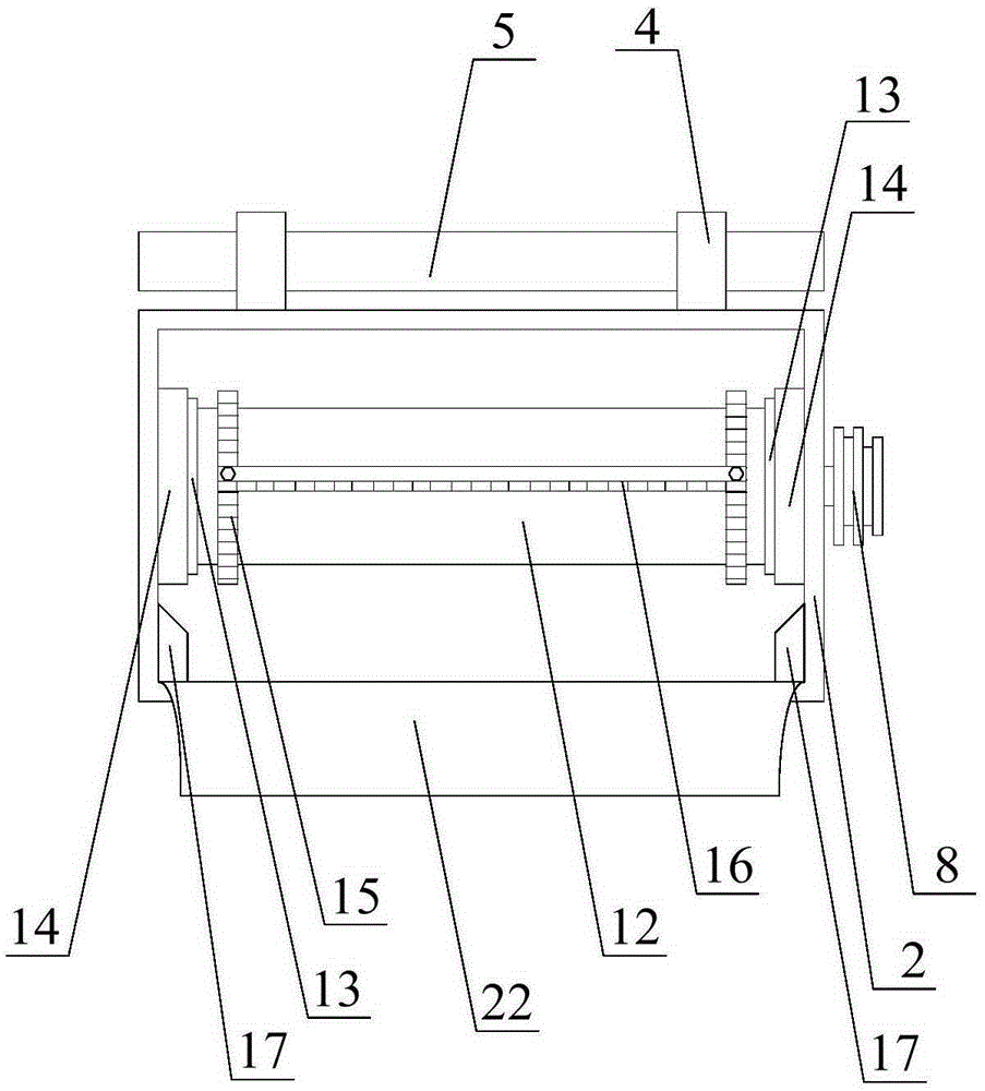
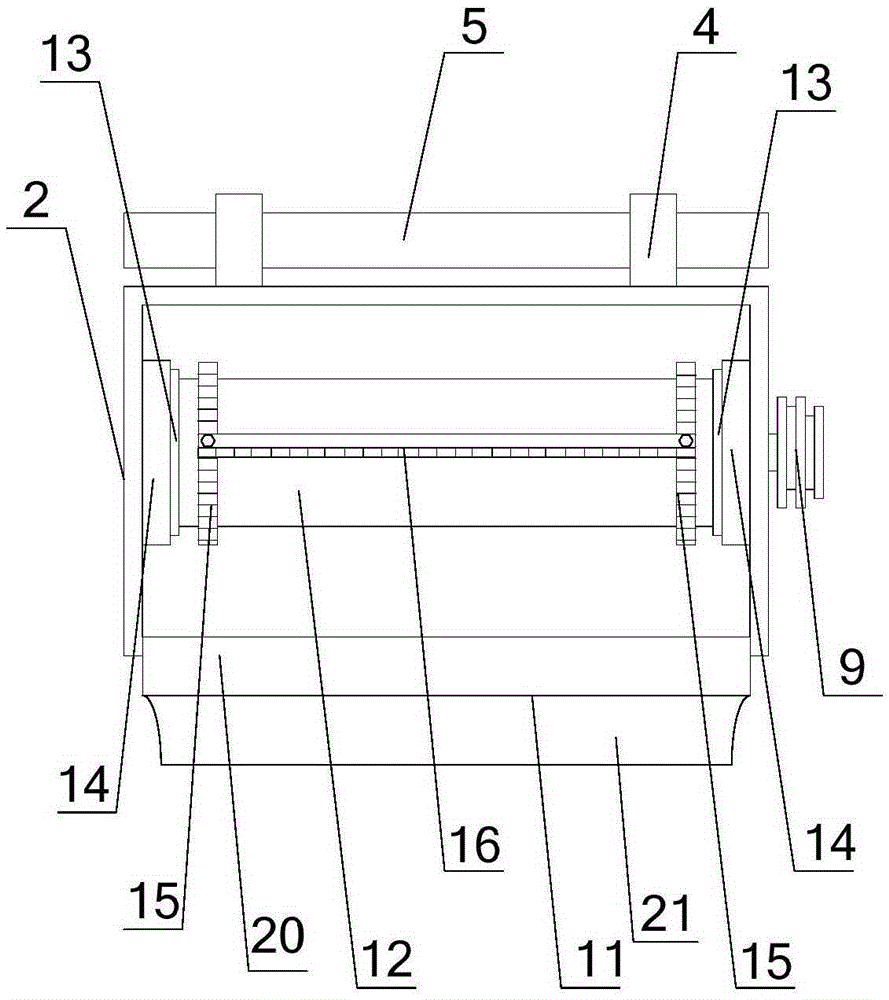
[0017] Such as Figure 1-3 As shown, the grass feeding mechanism of the combine harvester of the present invention includes a cutting table 1 and a conveying trough 2. A rotary shaft support 4 is provided above the grass inlet of the conveying trough 2, and a rotary shaft 5 is horizontally provided on the rotary shaft support 4 , The axial direction of the rotating shaft 5 is parallel to the upper edge of the grass inlet of the conveying trough 2; two fixed seats 3 are provided above the grass outlet of the cutting table 1, and the fixed seat 3 is provided with a semi-circular notch. The shaft heads at both ends are rotatably embedded in the semicircular notches of the two fixed seats 3 and locked by the arc-shaped lock 6; the lower edge of the inner side of the grass inlet of the conveying trough 2 is provided with an outwardly extending grass inlet Curved plate 22; the outer side of the lower edge of the grass outlet of the conveying trough 2 is provided with a rubber pad 10,...


PUM


Abstract

The invention provides a grass feeding mechanism of a combine harvester. The grass feeding mechanism comprises a cutting table and a transmitting groove, wherein a rotating shaft support is arranged above the grass feeding opening of the transmitting groove, a rotating shaft is arranged on the rotating shaft support, two fixed bases are arranged on the grass outlet opening of the cutting table, semi-circle groove openings are formed in the fixed bases, shaft heads on the two ends of the rotating shaft are embedded in the semi-circle groove openings of the two fixed bases, a grass feeding arc-shaped board is arranged on the lower edge position of the inner side of the grass feeding opening of the transmitting groove, a rubber cushion is arranged on the outer side of the lower edge of the grass outlet opening of the transmitting groove, an anti-leakage arc-shaped board is arranged on the inner side of the lower edge of the grass outlet opening of the transmitting groove, reversing rolling cylinders are respectively arranged at the grass feeding opening position and the grass outlet opening position inside the transmitting groove, two transmitting chains are arranged between the two reversing rolling cylinders, and a transmitting tooth rake is arranged between the two transmitting chains with equal distance. The grass feeding mechanism can effectively prevent the phenomenon that food leakage occurs at the butt joint of the cutting table and the transmitting groove and has a better application prospect.

Description

Technical field [0001] The invention relates to a component of a combine harvester, in particular to a grass feed mechanism of a combine harvester. Background technique [0002] The grass feed mechanism of the combine harvester includes the cutting platform and the conveying trough, but the problem of grain leakage often occurs between the grass inlet of the existing conveying trough and the grass exit of the cutting platform, and the cutting platform needs to be raised or lowered in real time during the working process. , The conveying trough is also required to be raised and lowered along with the cutting table. After long-term use, the joints between the cutting table and the conveying trough will become loose or worn. Summary of the invention [0003] The technical problem to be solved by the present invention is the problem of grain leakage at the joint between the header and the conveying trough in the prior art. [0004] In order to solve the above technical problems, the pr...

Claims


Application Information

Patent Timeline
Patent Type & Authority Patents(China)
IPC IPC(8): A01D41/16
Inventor 赵卫青朱凤年
Owner 宿迁诺泽建设工程有限公司
Learn More