Magnet door stopper hinge

A technology for attracting hinges and magnet doors, which is applied to hinges with pins, door/window accessories, and fastening devices for wing leaves, etc. It can solve the problem of inability to adjust the suction angle of door hinges and fixed hinges, and low practical performance. problem, to achieve the effect of convenient adjustment, good suction effect and convenient installation

Active Publication Date: 2015-02-04
PINGHU FUDA HARDWARE MFG CO LTD
View PDF10 Cites 10 Cited by
  • Summary
  • Abstract
  • Description
  • Claims
  • Application Information

AI Technical Summary

Problems solved by technology

[0003] The technical problem to be solved by the present invention is to provide a magnetic door-absorbing hinge, which can well solve the defects that the su

Method used


Image

  • Magnet door stopper hinge
  • Magnet door stopper hinge
  • Magnet door stopper hinge

Examples


Embodiment 1

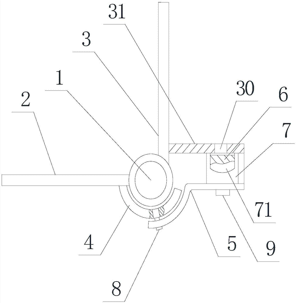
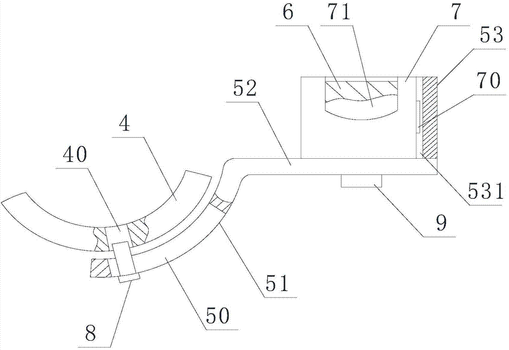
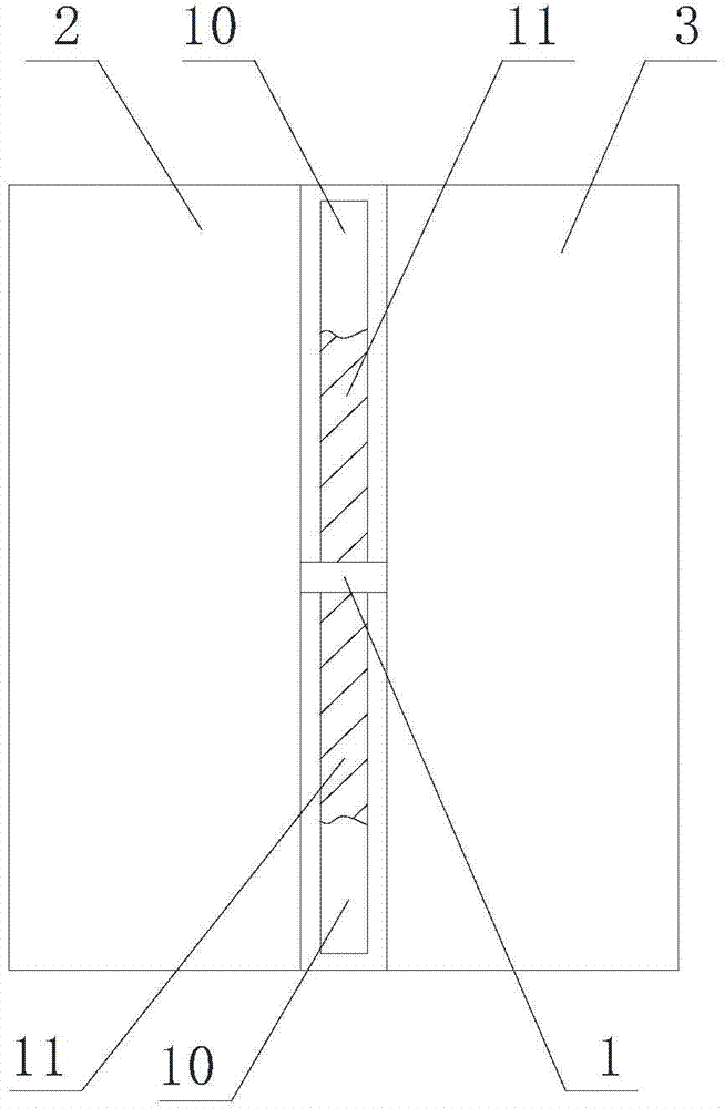
[0020] like figure 1 , figure 2 , image 3 As shown, the magnetic door suction hinge includes a hinge shaft 1, a fixed hinge leaf 2 for fixing and a door hinge leaf 3 for door fixing that are respectively rotatably connected to the hinge shaft 1, and the hinge shaft 1 is also provided with The steel sleeve 4, one end of the steel sleeve 4 is fixedly connected to the fixed hinge 2, and also includes an adjustment sleeve 5 which is rotatably connected to the steel sleeve for adjusting the suction angle between the door hinge 3 and the fixed hinge 2, so The adjustment sleeve 5 and the door hinge 3 form an included angle not less than 90°, the adjustment sleeve 5 is provided with a magnetic attraction device, and the magnetic attraction device is composed of at least two magnets 6 of different sizes. The hinge 3 is provided with a suction plate 31 that is attracted to the magnet 6. The suction plate 31 forms an angle of 90° with the door hinge. The adjustment sleeve 5 includes ...

Embodiment 2

[0022] As for the magnetic door suction hinge described in Embodiment 1, this embodiment has the following differences: Figure 4 As shown, when the door hinge 3 and the fixed hinge 2 are arranged in parallel, the adjustment sleeve 5 and the fixed hinge 2 are set at an angle of 90 to 140°, which can make the adjustment sleeve and the fixed hinge form a The included angle setting of 90-140° improves the practical performance and can adapt to different installation environments.

[0023] When in use, the fixed hinge 2 is fixedly installed on the wall, and the door hinge 3 is fixedly connected to the door. According to the requirements of the installation environment, the angle between the adjusting sleeve 5 and the fixed hinge is adjusted by screws, and the scale is displayed through the angle. Read the line to ensure that the angle is at the most suitable installation angle, and then adjust the installation sleeve 7 with the magnet 6 to move in the adjustment sleeve 5 through t...


PUM


Abstract

The invention relates to a magnet door stopper hinge, which comprises a hinged shaft, a fixed hinge leaf, a door hinge leaf, a steel bushing and a regulating sleeve; an included angle which is not less than 90 degrees is formed between the regulating sleeve and the door hinge leaf; the regulating sleeve is provided with a magnetic attraction device; the magnetic attraction device consists of magnets of at least two pipe reducers; the door hinge leaf is provided with a pull-in plate pulled in with the magnets; an included angle of 90 degrees is formed between the pull-in plate and the door hinge leaf; the regulating sleeve comprises an arc part and a horizontal part; the front end of the horizontal part is provided with a vertical part. The magnet door stopper hinge disclosed by the invention has the advantages that by rotating the regulating sleeve to change the angle, on the steel bushing, of the regulating sleeve, the pull-in angle between the door hinge leaf and the fixed hinge leaf is changed, so that the pull-in angle can be regulated according to different operating environments or installing environments; regulating is convenient; the pull-in plate arranged on the door hinge leaf is pulled in with the magnets, so that the opening angle of a door is reduced, and the damage to the door is reduced; the regulating sleeve is provided with the rotating arc part and the horizontal part provided with the magnets, and therefore, installation is convenient, the damage to the magnets is reduced, and the pull-in effect is best.

Description

technical field [0001] The invention relates to a magnetic door suction hinge. Background technique [0002] When the door is installed, the door and the door frame need to be fixedly connected through the door hinge. The current door hinge includes left and right hinges, and the left and right hinges are provided with through holes. Finally, the opening of the door is fixed by setting a door stopper on the wall. Although it can play a fixed role, the door stopper has an extended end, which is easy to break due to the heavy closing of the door, and it is easy for people to accidentally touch the door after closing the door. Suction, not only hurt the human body but also damage the door stopper, for this reason, a kind of door hinge that Chinese application number is 200820086649. It saves the installation of door stoppers, keeps the walls beautiful, and at the same time facilitates cleaning, and the cost of the door hinge is low, but when in use, the suction angle between t...

Claims


Application Information

Patent Timeline
IPC IPC(8): E05D3/02E05D11/06E05C17/56
CPCE05D3/02E05D11/06E05D11/1028E05D2011/1092
Inventor 徐国强
Owner PINGHU FUDA HARDWARE MFG CO LTD
Why Eureka
Try Eureka