A low voltage switch cabinet

A low-voltage switchgear and cabinet technology, applied in the field of switchgear, can solve problems such as operator discomfort, affect maintenance work efficiency, inconvenience, etc., and achieve the effects of simple structure, low cost, and convenient control.

Active Publication Date: 2017-01-18
GUANGDONG ZHONGXING ELECTRIC SWITCH
View PDF2 Cites 0 Cited by
  • Summary
  • Abstract
  • Description
  • Claims
  • Application Information

AI Technical Summary

Problems solved by technology

[0002] At present, most of the electrical components in the switch cabinet are installed on a mounting plate, and the mounting plate is then fixed on the back panel of the cabinet, or the electrical components are directly installed in the cabinet. Or during fault maintenance, the operator needs to put his upper body into the cabinet to maintain and check the devices in the cabinet, and only one operator can be accommodated, which is very inconvenient, brings discomfort to the operator, and affects Maintenance work efficiency

Method used


Image

  • A low voltage switch cabinet
  • A low voltage switch cabinet

Examples


Embodiment Construction

[0010] The present invention will be described in further detail below through specific implementation examples and in conjunction with the accompanying drawings.

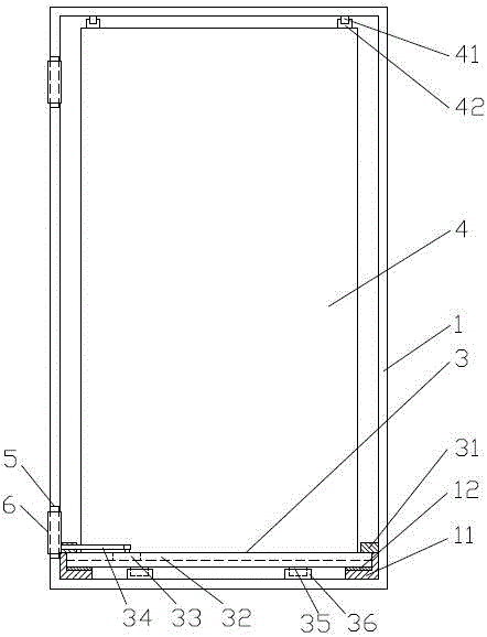
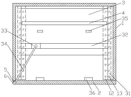
[0011] figure 1 , figure 2 It shows the low-voltage switchgear provided by the present invention, including a cabinet body 1, a cabinet door 2 rotatably connected to the cabinet body 1, a slide plate 3 located at the inner bottom of the cabinet body 1 and slidingly arranged, and a drive for driving the slide plate 3 to slide toward the side of the cabinet door. Mechanism, component mounting plate 4 on the slide plate 3; L-shaped tracks 11 are arranged on the left and right sides of the bottom plate of the cabinet body 1, the slide plate 3 is located on the L-shaped inner right angle surface of the two tracks 11, and the slide plate 3 and the track 11 A brass plate 12 is arranged between them, and filling holes 13 are arranged on the brass plate 12, and graphite is embedded in the filling hole 13; a limit pressure...


PUM


Abstract

The invention discloses a low voltage switch cabinet, and belongs to the switch cabinet technology field. The low voltage switch cabinet comprises a cabinet body, a cabinet door connected with the cabinet body in rotatable mode, a slide plate located at the bottom of the interior of the cabinet body and arranged in slide mode, a drive mechanism used to drive the slide plate to slide towards the cabinet door and a component installation plate located on the slide plate, wherein two L-shaped rails are arranged on the left side and the right side of the bottom plate of the cabinet door, a brass sheet is arranged between the slide plate and each rail, filling holes are distributed in each brass sheet, graphite is embedded in the filling holes, a limiting press plate which prevents the slide plate from being turned upwards is arranged above the slide plate, bumps are arranged on the bottom face of the slide plate, stop blocks corresponding to the bumps are arranged on the bottom plate of the cabinet body, a slide chute which extends in the direction coincident with the direction of the cabinet door when the cabinet door is closed is formed in the slide plate, a drive block is located in the slide chute, one end of a drive rod is hinged with the drive block, the other end of the drive rod is fixedly connected with the cabinet door, a slide rail is arranged at the top of the cabinet door, and a slide block matched with the slide rail is arranged at the top of the component installation plate. The low voltage switch cabinet is easy and convenient to operate and overhaul.

Description

technical field [0001] The invention relates to the technical field of switch cabinets, in particular to a low-voltage switch cabinet. Background technique [0002] At present, most of the electrical components in the switch cabinet are installed on a mounting plate, and the mounting plate is then fixed on the back panel of the cabinet, or the electrical components are directly installed in the cabinet. Or during fault maintenance, the operator needs to put his upper body into the cabinet to maintain and check the devices in the cabinet, and only one operator can be accommodated, which is very inconvenient, brings discomfort to the operator, and affects Maintenance work efficiency. Contents of the invention [0003] The object of the present invention is to provide a low-voltage switchgear to solve the above problems. [0004] In order to achieve the purpose of the present invention, the technical solution adopted is: a low-voltage switchgear, including a cabinet body, a...

Claims


Application Information

Patent Timeline
Patent Type & Authority Patents(China)
IPC IPC(8): H02B1/26
CPCH02B1/26
Inventor 韩永光
Owner GUANGDONG ZHONGXING ELECTRIC SWITCH
Why Eureka
Try Eureka