Predictive commutation failure prevention method, apparatus and device

A technology of commutation failure and prevention method, which is applied in the direction of circuit devices, AC network circuits, electrical components, etc., can solve problems such as unstable effects, achieve the effect of good commutation failure, reduce calculation interval, and improve calculation accuracy

Active Publication Date: 2015-02-04
XUCHANG KETOP DETECTION TECH CO LTD
View PDF3 Cites 13 Cited by
  • Summary
  • Abstract
  • Description
  • Claims
  • Application Information

AI Technical Summary

Problems solved by technology

[0013] The purpose of the present invention is to provide a predictive commutation failure prevention method to

Method used


Image

  • Predictive commutation failure prevention method, apparatus and device
  • Predictive commutation failure prevention method, apparatus and device
  • Predictive commutation failure prevention method, apparatus and device

Examples


Embodiment 1

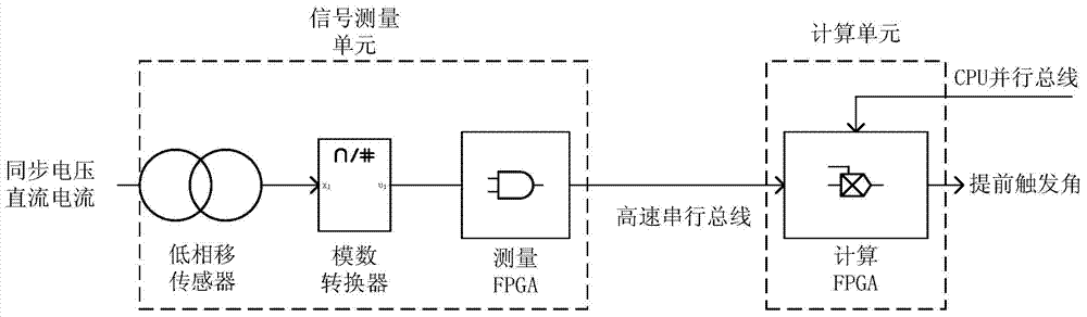
[0054] Since the UHV DC transmission project requires the separation of the measurement system and the control system, the predictive commutation failure prevention instrument is also divided into a signal measurement unit and a calculation unit. The signal measurement unit is connected in communication with the calculation unit. The improvement of this embodiment is that at least the calculation unit is implemented by FPGA.

[0055] Specifically, such as image 3 As shown in the embodiment, the signal measurement unit includes a phase shift sensor, an analog-to-digital converter, and a measurement FPGA connected in sequence, and the calculation unit includes a calculation FPGA. The measurement FPGA is connected to the calculation FPGA via a high-speed serial bus.

[0056] The calculation of the commutation margin area is completely implemented using a large-scale field programmable gate array FPGA. Because of the parallel computing characteristics of FPGA, it can calculate ...

Embodiment 2

[0058] In the prior art, the current time and the half-wave period are measured by using the zero-crossing point of the commutation voltage, which is easily affected by the harmonics of the commutation voltage and the distortion of the zero-crossing point.

[0059] In this embodiment, the signal measurement unit and the calculation unit of the predictive commutation failure prevention instrument are composed of existing hardware. The phase voltage is in an inertial synchronous state, and the stable output of the phase-locked loop eliminates the influence of voltage harmonics and zero-crossing distortion.

[0060] Phase-locked synchronous components are the most important basic components of DC transmission, such as Figure 4 As shown, it mainly includes anti-aliasing filter and interpolation sampling link (part a), digital filter for positive sequence filtering and harmonic filtering (part b), amplitude and phase calculation of AC voltage (part c) , AC voltage frequency track...

Embodiment 3

[0075] Since the commutation voltage and DC current after triggering will fluctuate, the actual commutation margin area is relatively small, and the effect of preventing commutation failure is weakened. Therefore, nonlinear compensation is performed on the output angle to balance the influence of DC current fluctuations. In this embodiment, the signal measurement unit and the calculation unit of the predictive commutation failure prevention instrument are both composed of existing hardware, and the improvement lies in adding nonlinear compensation of the output angle in the output link. Those skilled in the art can choose the compensation method and compensation degree.


PUM


Abstract

The invention relates to a predictive commutation failure prevention method, apparatus and device. In the method, a needed angle Alpha is taken from output of a phase-locked loop and the zero crossing point and half-period time of an AC synchronous voltage no longer need to be measured. Because the commutation margin areas of 12 bridge arms are calculated at the same time, the pre-trigger valve number does not need to be considered anymore, and minimum values of the 12 areas are selected so that the effect of commutation failure prevention is better. DC shaping and a nonlinear compensation technology are used to correct post-trigger commutation voltage and DC fluctuation so as to enhance the commutation failure prevention capability.

Description

technical field [0001] The invention relates to the field of prevention of predictive commutation failure in direct current transmission, in particular to a method, device and equipment for preventing predictive commutation failure. Background technique [0002] Commutation failure is one of the most common failures of inverters in DC transmission systems. Mainly in the inverter, when the phase is commutated between the two bridge arms, if the valve that has just exited conduction fails to recover the blocking ability within the time of reverse voltage action, or the commutation process fails during the reverse voltage If it can be completed, the valve that was originally scheduled to exit will be re-conducted when the valve voltage changes to positive. Failure of commutation will lead to adverse consequences such as reduction of DC voltage, reduction of transmission power, increase of current, shortening of the life of the converter valve, DC bias of the converter transfor...

Claims


Application Information

Patent Timeline
IPC IPC(8): H02J3/36
CPCY02E60/60H02J3/36H02J2003/365
Inventor 李亚萍姚致清胡卫东李志勇周鹏鹏王峥夏王伟庄良文傅润炜贾德峰
Owner XUCHANG KETOP DETECTION TECH CO LTD
Why Eureka
Try Eureka