Predictive commutation failure prevention method and device
A technology of commutation failure and prevention method, which is applied in the direction of emergency treatment AC circuit layout, power transmission AC network, etc. The effect of improving calculation accuracy
- Summary
- Abstract
- Description
- Claims
- Application Information
AI Technical Summary
Problems solved by technology
Method used
Image
Examples
Embodiment 1
[0055] Since the UHV DC transmission project requires the separation of the measurement system and the control system, the predictive commutation failure prevention instrument is also divided into a signal measurement unit and a calculation unit. The signal measurement unit is connected in communication with the calculation unit. The improvement of this embodiment is that at least the calculation unit is implemented by FPGA.
[0056] Specifically, such as image 3 As shown in the embodiment, the signal measurement unit includes a phase shift sensor, an analog-to-digital converter, and a measurement FPGA connected in sequence, and the calculation unit includes a calculation FPGA. The measurement FPGA is connected to the calculation FPGA via a high-speed serial bus.
[0057] The calculation of the commutation margin area is completely implemented using a large-scale field programmable gate array FPGA. Because of the parallel computing characteristics of FPGA, it can calculate ...
Embodiment 2
[0059] In the prior art, the current time and the half-wave period are measured by using the zero-crossing point of the commutation voltage, which is easily affected by the harmonics of the commutation voltage and the distortion of the zero-crossing point.
[0060] In this embodiment, the signal measurement unit and the calculation unit of the predictive commutation failure prevention instrument are composed of existing hardware. The phase voltage is in an inertial synchronous state, and the stable output of the phase-locked loop eliminates the influence of voltage harmonics and zero-crossing distortion.
[0061] Phase-locked synchronous components are the most important basic components of DC transmission, such as Figure 4 As shown, it mainly includes anti-aliasing filter and interpolation sampling link (part a), digital filter for positive sequence filtering and harmonic filtering (part b), amplitude and phase calculation of AC voltage (part c) , AC voltage frequency track...
Embodiment 3
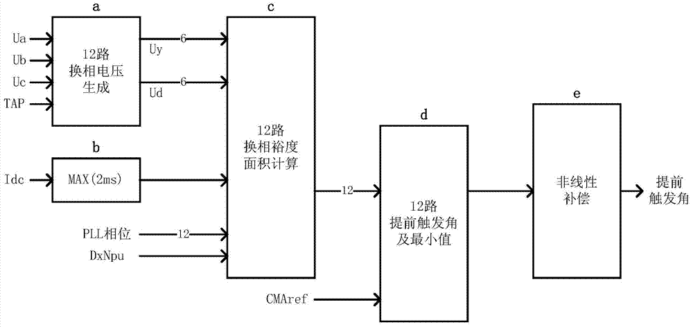
[0076] Since the commutation voltage and DC current after triggering will fluctuate, the actual commutation margin area is relatively small, and the effect of preventing commutation failure is weakened. Therefore, nonlinear compensation is performed on the output angle to balance the influence of DC current fluctuations. In this embodiment, the signal measurement unit and the calculation unit of the predictive commutation failure prevention instrument are both composed of existing hardware, and the improvement lies in adding nonlinear compensation of the output angle in the output link. Those skilled in the art can choose the compensation method and compensation degree.
PUM
 Abstract
Description
Claims
Application Information
 - R&D
- Intellectual Property
- Life Sciences
- Materials
- Tech Scout
- Unparalleled Data Quality
- Higher Quality Content
- 60% Fewer Hallucinations
Browse by: Latest US Patents, China's latest patents, Technical Efficacy Thesaurus, Application Domain, Technology Topic, Popular Technical Reports.
© 2025 PatSnap. All rights reserved.Legal|Privacy policy|Modern Slavery Act Transparency Statement|Sitemap|About US| Contact US: help@patsnap.com


