Hammer pulling device

A hammer body and sliding rod technology, applied in the direction of hand-held tools, manufacturing tools, etc., can solve the problems of reduced service life, difficult to pull out bearings, time-consuming and labor-intensive problems, and achieve the effect of simple structure and easy operation

Inactive Publication Date: 2015-02-11
SHAANXI NANLIANG MINING
View PDF14 Cites 2 Cited by
  • Summary
  • Abstract
  • Description
  • Claims
  • Application Information

AI Technical Summary

Problems solved by technology

[0002] In commonly used mining machinery, such as coal shearers, bearings are important transmission components. The bearings are subject to severe impact and long-term wear during the mining process, which will lead to a decrease in service life, so the bearings need to be disassembled and replaced.
However, after the bearing is used for a long time, it is difficult to pull out the bearing due to rust, corrosion and other reasons.
The existing bearing removal method is generally to use a sledgehammer to knock out the bearing, and then manually pull out the bearing. This method is not only time-consuming and laborious, but also difficult to pull out the bearing.

Method used


Image

  • Hammer pulling device
  • Hammer pulling device
  • Hammer pulling device

Examples


Embodiment 1

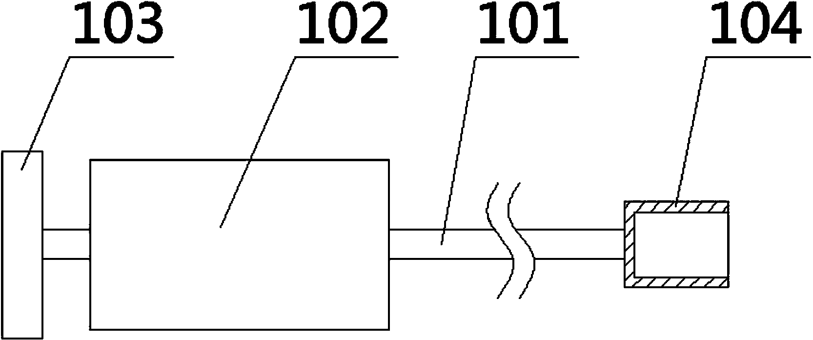
[0038] figure 1 shows the structure of the hammer device provided by Embodiment 1 of the present invention; please refer to figure 1 , Embodiment 1 of the present invention provides a pull hammer device, the pull hammer device is mainly used for the removal of coal shearer bearings. The pulling hammer device includes a sliding rod 101 and a hammer body 102 slidably connected with the sliding rod 101 . One end of the sliding rod 101 is provided with a baffle 103 , and the other end is provided with a sleeve 104 . The sleeve 104 is provided with a fastening structure for fastening the bearing.

[0039] When using the pull hammer device, the bearing is fastened by the fastening structure on the sleeve 104, and then the hammer body 102 is pulled quickly and forcefully, so that the hammer body 102 slides along the slide bar 101 until it hits the baffle plate 103, and the hammer body 102 is applied to The large instantaneous force of the baffle plate 103 makes the baffle plate 10...

Embodiment 2

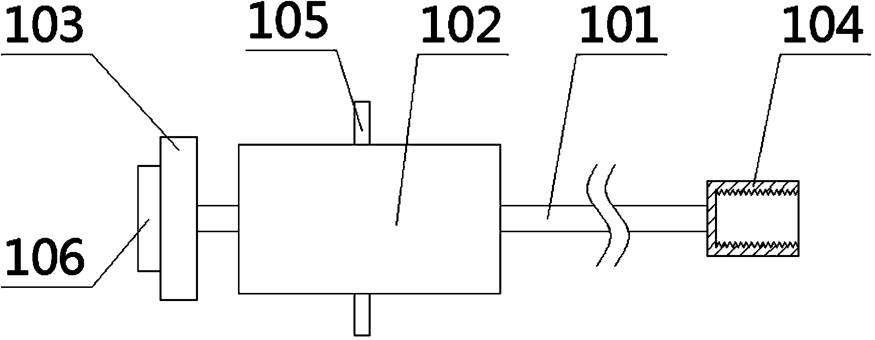
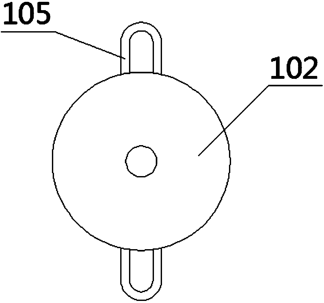
[0042] figure 2 Shows the structure of the pull hammer device provided by Embodiment 2 of the present invention; image 3 Shows the top view structure of the hammer body 102 of the hammer device provided in Embodiment 2 of the present invention; please refer to figure 2 with image 3 , Embodiment 2 of the present invention provides a pull hammer device, which includes all the technical features of the pull hammer device provided in Embodiment 1, and the pull hammer device also includes the following technical features:

[0043] The inner wall of the sleeve 104 is provided with an inner wire. By setting the inner wire on the inner wall of the sleeve 104, the inner wire can cooperate with the bearing, so that the sleeve 104 and the bearing are screwed together to achieve the purpose of fastening the bearing so as to pull out the bearing.

[0044] The sleeve 104 and the baffle 103 are integrally welded with the sliding rod 101 respectively. Sleeve 104, baffle plate 103, sli...

Embodiment 3

[0055] Embodiment 3 of the present invention provides a pull-hammer device, which differs from the pull-hammer device provided in Embodiment 2 only in the structure of the sleeve 104 .

[0056] Figure 4 shows the structure of the pull hammer device provided by Embodiment 3 of the present invention; please refer to Figure 4 , The side wall of the sleeve 104 of the pull hammer device provided in Embodiment 3 of the present invention is provided with at least two threaded holes 107 that cooperate with fastening screws. By setting at least two threaded holes 107 on the side wall of the sleeve 104, when fastening the bearing, first put the sleeve 104 on the bearing, and then screw the screw through the threaded hole 107 until the screw clamps the bearing, thereby achieving The purpose of fastening the bearings is to pull out the bearings.

[0057] There are four threaded holes 107 and they are evenly distributed symmetrically to the center. By setting the threaded holes 107 to...


PUM


Abstract

The invention provides a hammer pulling device, and belongs to the field of bearing disassembly devices of mining machinery. The device comprises a sliding rod and a hammer body connected with the sliding rod in a sliding manner, wherein a baffle is arranged at one end of the sliding rod; a sleeve is arranged at the other end of the sliding rod; the sleeve is provided with a fastening structure used for fastening a bearing. When the hammer pulling device is in use, the bearing is fastened through the fastening device on the sleeve, and then the hammer body is rapidly and forcibly pulled, so that the hammer body slides along the sliding rod to impact the baffle, the hammer body applies strong instantaneous apply force to the baffle, so that the baffle drives the sliding rod, the sliding rod drives the sleeve, and the sleeve has a lifting effect on the bearing, thereby pulling out the bearing. The hammer pulling device can properly disassemble bearings on mining machinery, has a simple structure, and is easy to operate.

Description

technical field [0001] The invention relates to the field of bearing removal devices for mining machinery, in particular to a pull hammer device. Background technique [0002] In commonly used mining machinery, such as coal shearers, bearings are important transmission components. The bearings are subject to severe impact and long-term wear during the mining process, which will lead to a decrease in service life. Therefore, the bearings need to be disassembled and replaced. However, after the bearing has been used for a long time, due to reasons such as rust and corrosion, the bearing is difficult to pull out. The existing bearing dismounting method generally uses a sledgehammer to knock, and then manually pulls out the bearing. This method is not only time-consuming and laborious, but also difficult to pull out the bearing. Contents of the invention [0003] The present invention provides a pull hammer device, aiming to improve the above problems. [0004] The present i...

Claims


Application Information

Patent Timeline
Patent Type & Authority Applications(China)
IPC IPC(8): B25B27/067
CPCB25B27/06
Inventor 杨文清付二军李自雄
Owner SHAANXI NANLIANG MINING
Why Eureka
Try Eureka