Recording apparatus

A recording device and recording head technology, applied in printing devices, kerning mechanisms, printing, etc., can solve problems such as not being able to obtain visual effects well

Active Publication Date: 2015-02-11
SEIKO EPSON CORP
View PDF10 Cites 0 Cited by
  • Summary
  • Abstract
  • Description
  • Claims
  • Application Information

AI Technical Summary

Problems solved by technology

[0008] Therefore, if recording is started with the cut surface of the incomplete semi-cylindrical lens element as a reference position, the image that should be recorded in one lens element is recorded across other adjacent lens elements, and the result cannot be good. to obtain the above-mentioned various visual effects

Method used


Image

  • Recording apparatus
  • Recording apparatus
  • Recording apparatus

Examples


Embodiment Construction

[0085] Hereinafter, one embodiment of the present invention will be described based on the drawings. However, the present invention is not limited to the embodiments described below. Various modifications can be made within the scope of the invention described in the technical solution, and these modifications are also included in the present invention. Within the scope of the above, an embodiment of the present invention will be described below on the premise.

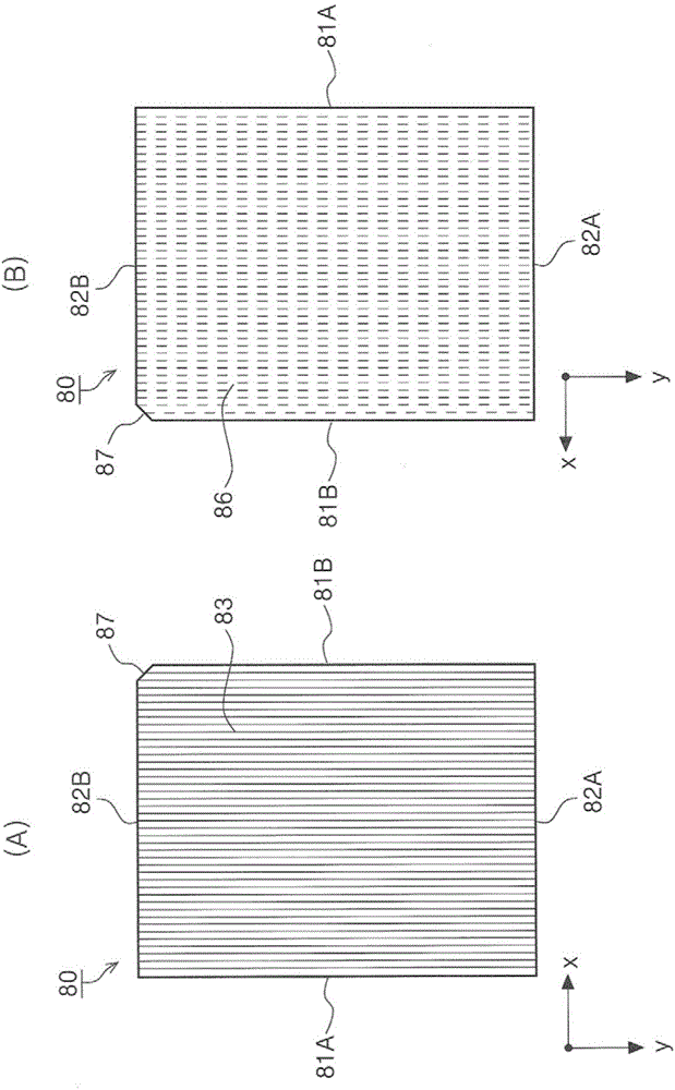
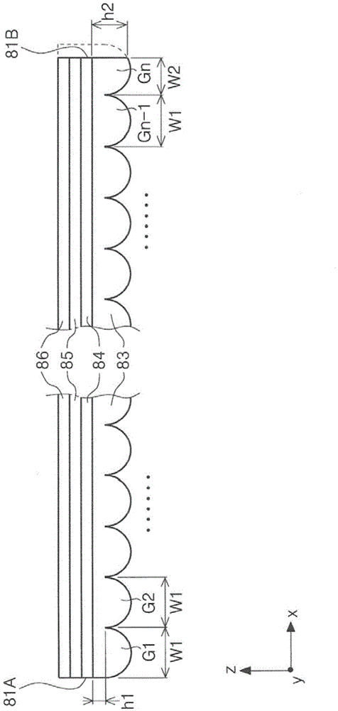
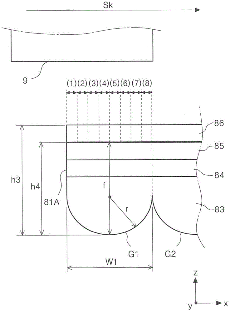
[0086] figure 1 (A) is a plan view of the lens sheet 80 as an example of the recording medium according to the present invention viewed from the lens layer 83 side, figure 1 (B) is a plan view of the lens sheet 80 viewed from the ink absorbing layer 86 side, figure 2 It is a cross-sectional view seen by cutting the lens sheet 80 with the x-z plane, image 3 It is a cross-sectional view seen by cutting one end face of the lens sheet 80 in the x direction with the x-z plane, Figure 4 (A), (B), and (C) are diagrams showing ...


PUM


Abstract

A lens sheet is provided with a lens layer which is formed by arranging lenses, which extend in a y direction as a first direction, in a plurality of lines in an x direction as a second direction which is a direction which is orthogonal to the first direction, and an ink absorbing layer which configures a surface on the opposite side with regard to a surface which is configured by the lens layer, where the thickness of an edge which is an end surface on one side of the lens layer in the x direction is thinner than the thickness of an edge which is an end surface on the other side. The printer performs recording from the edge which is a reference side toward the edge on the opposite side.

Description

Technical field [0001] The present invention relates to a recording device that performs recording on a recording medium. One surface of the recording medium is a lens layer composed of a plurality of lenses, and the other surface is composed of a recording layer capable of recording with a recording head. Background technique [0002] In printers as an example of recording devices that perform recording on a recording medium, in particular inkjet printers, some can select a bidirectional recording mode and a unidirectional recording mode. In the bidirectional recording mode, the recording medium and the recording head Both the period when the relative movement in the predetermined direction and the period when the movement in the direction opposite to the predetermined direction cause the ink to be discharged from the recording head, in this unidirectional recording mode, only when the recording medium and the recording head face each other The ink is discharged from the recordi...

Claims


Application Information

Patent Timeline
Patent Type & Authority Applications(China)
IPC IPC(8): B41J2/01B41J3/407
CPCB41J11/009B41J19/142B41J13/0018B41J2/04501B41J13/103B41J3/60
Inventor 吉久靖彦山田克己城取洋铃木胜仁曾根原富雄
Owner SEIKO EPSON CORP
Why Eureka
Try Eureka