
Suspension centre joint

A point joint, direct technology, applied in the direction of thin plate connection, connecting components, load hanging components, etc., can solve the problems that cannot be effectively satisfied, and achieve the effect of large bearing capacity, flexible connection form and reliable lifting connection

Inactive Publication Date: 2015-02-11
BEIJING INST OF SPACECRAFT SYST ENG
View PDF5 Cites 3 Cited by
  • Summary
  • Abstract
  • Description
  • Claims
  • Application Information

AI Technical Summary

Problems solved by technology

[0002] In some specific spacecraft structures, due to the need to bear and transmit loads, the intersecting position of multiple structural plates is used as the connection point of the lifting point. The interface of the point itself, the structure configuration of the lifting point that provides threaded holes and pin holes in the current spacecraft structure cannot effectively meet the needs of multiple interfaces and large loads at the same time

Method used


Image

  • Suspension centre joint
  • Suspension centre joint
  • Suspension centre joint

Examples


Embodiment Construction

[0022] The suspension point joint according to the present invention will be further described in detail with reference to the accompanying drawings and specific embodiments.

[0023] In order to realize the effective connection of multiple decks in the spacecraft, provide a horizontally supported large load interface and ensure the smooth lifting of the spacecraft, the lifting point joint structure of the present invention is proposed, and the specific implementation is as follows.

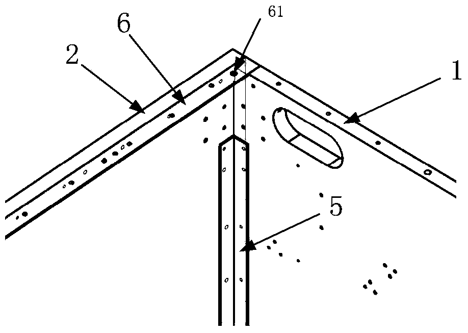
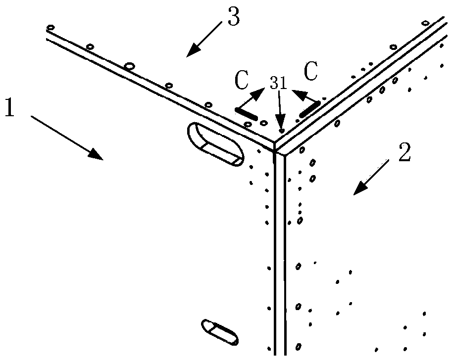
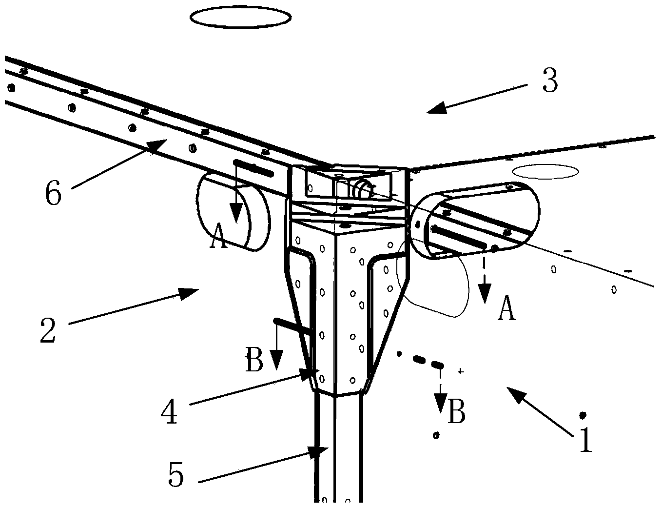
[0024] The lifting point joint according to the present invention is used for lifting and connecting the load to be lifted with the first side plate 1, the second side plate 2 and the top plate 3, referring to Figure 1a and Figure 1b As shown, in the load to be hoisted, the first side panel 1 and the second side panel 2 are vertically connected through the side panel reinforcement angle strip 5, and it can be seen from the figure that the side panel reinforcement angle strip 5 is connected on th...


PUM


Abstract

The invention provides a suspension centre joint which is used for lifting connection of a to-be-lifted load comprising a first side plate, a second side plate and a top plate. In the to-be-lifted load, the first side plate is vertically connected with the second side plate through a side plate reinforcing bar; the top plate is connected to the top surfaces of the first and second side plates; moreover, the top plate is connected with the second side plate through a top plate connecting angle shaft, while the top plate is directly connected with the first side plate through screws. The suspension centre joint disclosed by the invention is arranged between the first side plate and the second side plate. A bolt of a lifting device can be connected with a threaded hole formed in the top surface of the suspension centre joint after passing through the top plate and a connecting through hole in the top plate connecting angle shaft, thus the lifting function is realized. The suspension centre joint disclosed by the invention can provide suspension of a connecting interface of a storage box pull rod in a limited structure and bear a large load caused by the suspension, and also satisfies the structural connection and reinforcement requirements of clapboards, the side plates and the top plate.

Description

technical field [0001] The invention belongs to the technical field of mechanical structures, and in particular relates to a lifting point joint, in particular to a lifting point structure suitable for lunar landers and other spacecraft structures with a single joint to realize multiple interfaces and multiple concentrated large loads. Background technique [0002] In some specific spacecraft structures, due to the need to bear and transmit loads, the intersecting position of multiple structural plates is used as the connection point of the lifting point. The interface of the point itself, the structure configuration of the lifting point that provides threaded holes and pin holes in the current spacecraft structure cannot effectively meet the needs of multiple interfaces and large loads at the same time. Contents of the invention [0003] The technical problem to be solved in the present invention is to provide a lifting point joint for the deficiencies of the prior art. T...

Claims


Application Information

Patent Timeline
Patent Type & Authority Applications(China)
IPC IPC(8): B66C1/10B64G1/62
CPCB64G1/22B66C1/10F16B5/0291
Inventor 邓宇华盛聪柴洪友曾惠忠陈天智
Owner BEIJING INST OF SPACECRAFT SYST ENG
Learn More