
Installation structure and installation method of radial magnetic bearing and radial sensor

A radial sensor and installation structure technology, applied in the mechanical field, can solve problems such as large errors and difficulty in meeting design requirements, and achieve the effect of reducing coaxiality errors

Inactive Publication Date: 2015-02-11
NANJING CIGU TECH CORP LTD
View PDF6 Cites 5 Cited by
  • Summary
  • Abstract
  • Description
  • Claims
  • Application Information

AI Technical Summary

Problems solved by technology

Therefore, the coaxiality error between the inner cylindrical surface of the radial magnetic bearing and the inner cylindrical surface of the radial sensor bracket is X1+X2+X3+X4, the error is large, and it is difficult to meet the design requirements

Method used


Image

  • Installation structure and installation method of radial magnetic bearing and radial sensor
  • Installation structure and installation method of radial magnetic bearing and radial sensor

Examples


Embodiment Construction

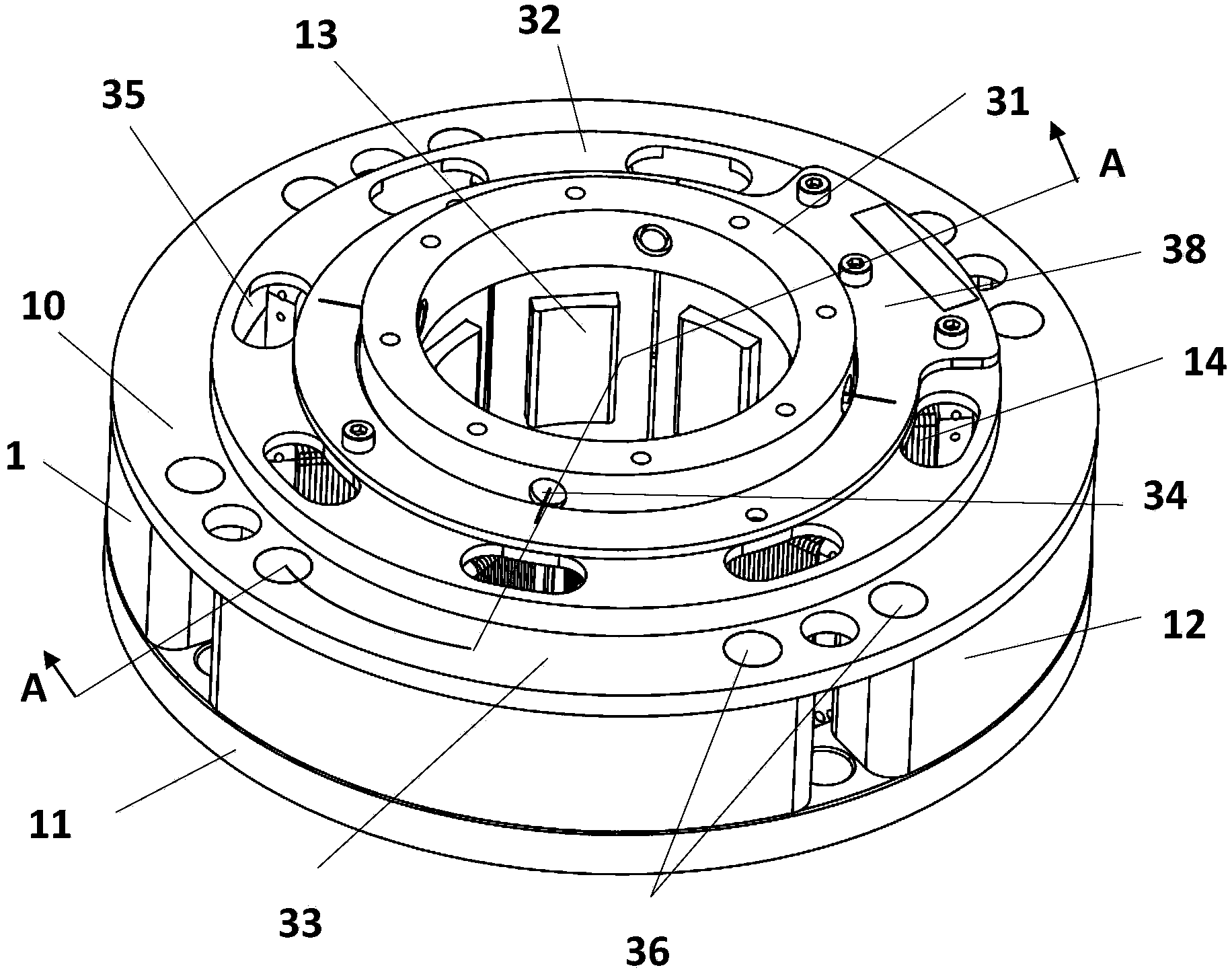
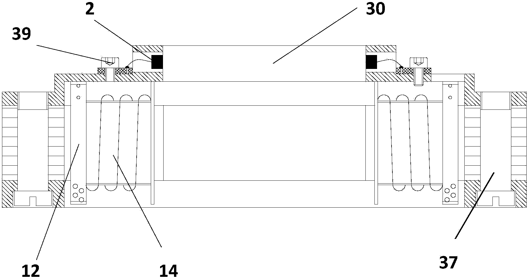
[0018] Please refer to figure 1 and figure 2 As shown, in the installation structure of the radial magnetic bearing and the radial sensor of the present invention, the radial magnetic bearing 1 is a hollow structure in which the upper and lower surfaces pass through as a whole, which includes an upper pressing plate 10, a lower pressing plate 11, and an upper pressing plate 10 and a lower pressing plate. 11 and spaced apart silicon steel sheets 12, on the inner surface of the silicon steel sheet 12, a bobbin 13 is installed, and a coil 14 is wound on the bobbin 13, wherein the outer arc surface of the silicon steel sheet 12 is surrounded to form a The outer cylindrical surface of the radial magnetic bearing 1 is surrounded by the inner end of the coil bobbin 13 to form the inner cylindrical surface of the radial magnetic bearing 1 . The upper pressing plate 10 is a stepped circular pressing plate, and a round hole 30 penetrating through the upper and lower surfaces of the up...


PUM


Abstract

The invention discloses an installation structure of a radial magnetic bearing and a radial sensor and an installation method of the installation structure of the radial magnetic bearing and the radial sensor. The installation structure is characterized in that the radial magnetic bearing comprises an upper pressing plate, a lower pressing plate and silicon steel sheets, wherein coil frameworks are respectively installed on the inner side surfaces of the silicon steel sheets; coils are respectively intertwined on the coil frameworks; after the external circular arc surfaces of the silicon steel sheets are surrounded, the external cylindrical surface of the radial magnetic bearing is formed; after the inner side tail ends of the coil frameworks are surrounded, the internal cylindrical surface of the radial magnetic bearing is formed; the upper pressing plate comprises an upper step, a middle step and a lower step; a circular hole is formed in the middle of the upper pressing plate; a plurality of through holes are uniformly formed at intervals in the periphery of the round hole in the upper step; a plurality of groups of penetration holes are formed in the lower step; two outmost holes among the penetration holes are pin holes; the pin holes are also formed in the places, corresponding to the pin holes in the upper pressing plate, of the lower pressing plate; cylindrical pins are arranged in the pin holes in the lower pressing plate and the pin holes in the upper pressing plate in a penetrating mode; a magnetic bearing circuit board is arranged on the middle step; after the radial sensor is placed in the through holes, the tail end thereof is electrically connected onto the magnetic bearing circuit board.

Description

Technical field: [0001] The invention relates to an installation structure and an installation method of a radial magnetic bearing and a radial sensor, belonging to the technical field of machinery. Background technique: [0002] In the existing structure, the radial magnetic bearing and the radial sensor are processed in two parts, and then respectively installed into the motor housing, wherein the outer cylindrical surface of the radial magnetic bearing and the inner cylindrical surface of the motor housing Clearance fit positioning, the axis of the inner cylindrical surface of the radial magnetic bearing and the axis of the outer cylindrical surface of the radial magnetic bearing produce a coaxiality processing error X1 due to machining errors. After the radial magnetic bearing is installed into the motor housing, the radial magnetic bearing The axis of the outer cylindrical surface of the bearing and the axis of the inner cylindrical surface of the motor housing will pro...

Claims


Application Information

Patent Timeline
IPC IPC(8): F16C32/04F16C41/00F16C43/00
Inventor 丁嵩徐龙祥刘淑云董继勇吴立华
Owner NANJING CIGU TECH CORP LTD
Learn More