
Reduction transmission bearing

A deceleration transmission and bearing technology, which is applied in the direction of bearings, rolling contact bearings, rotating bearings, etc., can solve the problems of large overall structure and high manufacturing cost, and achieve the effects of shortening the axial width, simplifying the structure, and preventing axial separation

Active Publication Date: 2018-02-27
国际精工股份有限公司
View PDF10 Cites 0 Cited by
  • Summary
  • Abstract
  • Description
  • Claims
  • Application Information

AI Technical Summary

Problems solved by technology

However, the two steel rings are side-by-side, and axial separation will occur. Therefore, other components such as a casing must be installed to prevent the two steel rings from axial separation, resulting in a larger overall structure and higher manufacturing costs. high

Method used


Image

  • Reduction transmission bearing
  • Reduction transmission bearing
  • Reduction transmission bearing

Examples


Embodiment Construction

[0055] The present invention will be further described below in conjunction with the accompanying drawings and specific embodiments, so that those skilled in the art can better understand the present invention and implement it, but the examples given are not intended to limit the present invention.

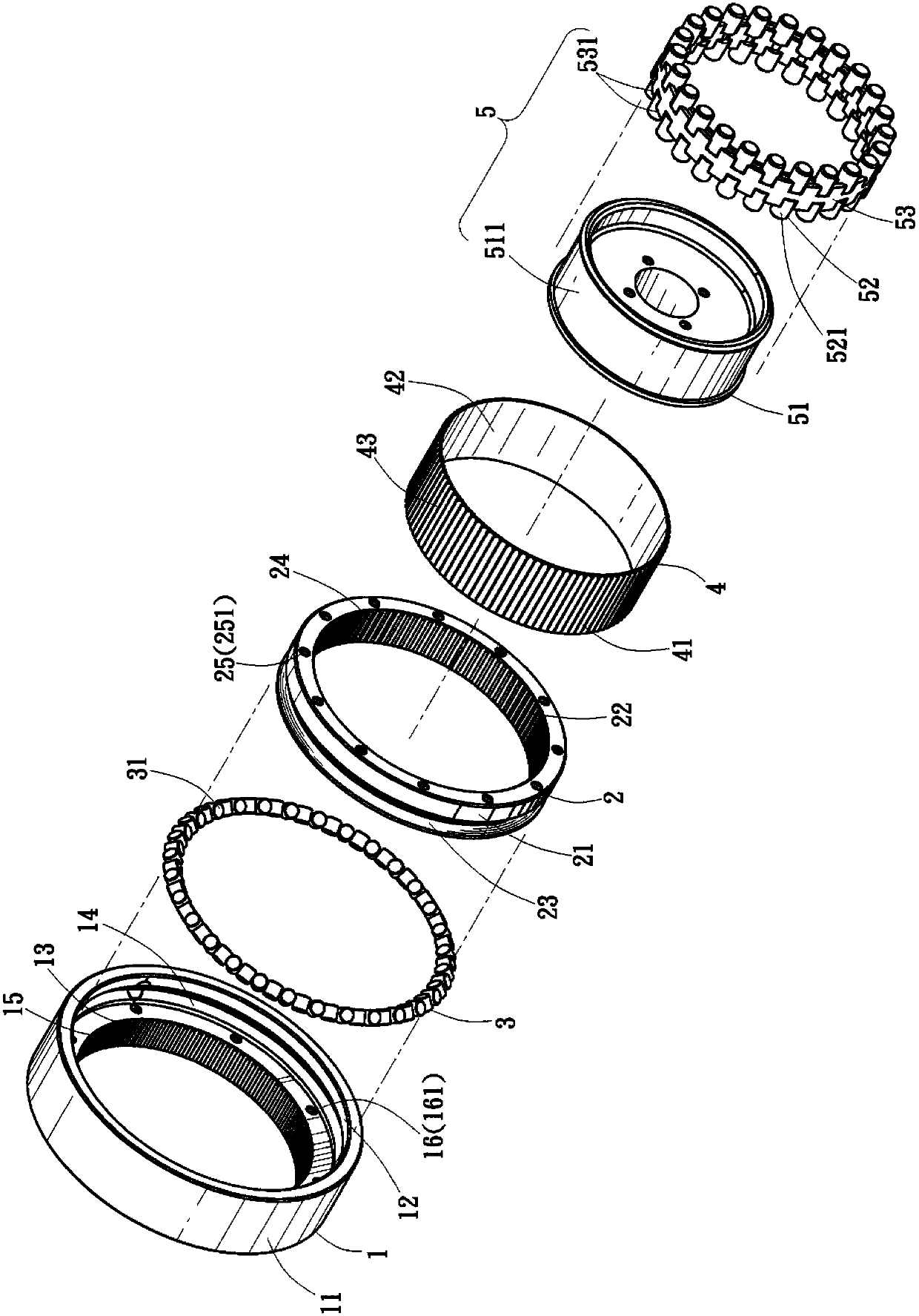
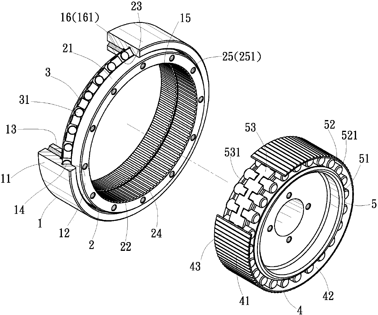
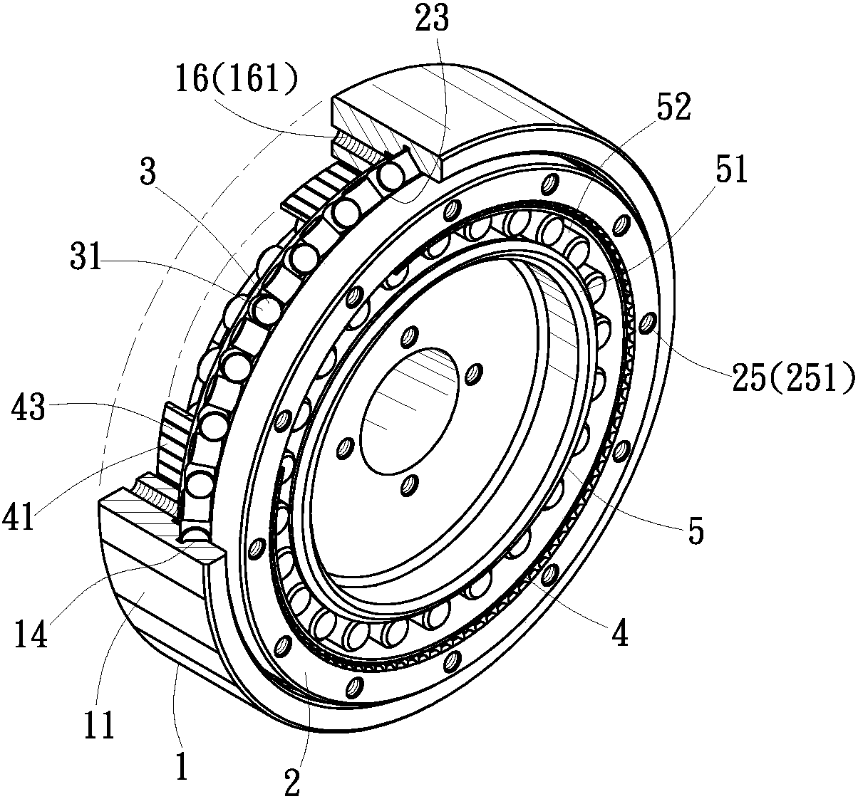
[0056] Such as figure 1 , figure 2 and image 3 As shown, the first preferred embodiment of the reduction transmission bearing of the present invention includes a first outer ring 1, a second outer ring 2, a plurality of first rolling elements 3, an inner ring 4 and a harmonic 5 (wave generator), where:

[0057]The first outer ring 1 is a torus, which has a first outer ring surface 11, a first inner ring surface 12 and a second inner ring surface 13, and the diameter of the first inner ring surface 12 is larger than that of the second inner ring surface. The diameter of the ring surface 13 is such that the first outer ring 1 forms a stepped inner hole. And the first inner rin...


PUM


Abstract

The invention provides a gearing-down bearing. The gearing-down bearing comprises a first outer ring and a second outer ring which are sleeved with each other, rolling parts are arranged between the first outer ring and the second outer ring and prevent the first outer ring and the second outer ring from axially or radially separating, and the inner ring surfaces of the first outer ring and the second outer ring are provided with inner teeth different in the tooth number. The gearing-down bearing further comprises an inner ring and a wave generator, wherein the inner ring is rotationally arranged in the first outer ring and the second outer ring, the outer ring surface of the inner ring is provided with outer teeth, the wave generator is rotationally arranged in the inner ring and can push the inner ring when rotating, and the outer teeth of at least one part of the inner ring are meshed with the inner teeth of the first outer ring and the second outer ring, thus, transmission of high gearing-down ratio can be realized by rotation of the difference of the tooth number. The first outer ring and the second outer ring are sleeved together, friction force of mutual rotation of the first outer ring and the second outer ring is reduced, stability in mutual sleeving is enhanced, axial separation of the first outer ring and the second outer ring is effectively prevented, and the objectives for downsizing and simplifying the structure can be realized.

Description

technical field [0001] The invention relates to a reduction transmission bearing, in particular to a design of a transmission assembly which can be stably supported by a transmission mechanism and also has the function of variable speed transmission. Background technique [0002] As the rotating component of the rotating shaft, the existing bearing can provide the radial and axial support of the rotating shaft to maintain the center position of the shaft, improve the sliding property of the rotating shaft and reduce the friction force. In addition, the general bearing does not with other functions. Therefore, when the bearing is used in a deceleration transmission mechanism, for example, if the motor is to decelerate to drive a transmission shaft to rotate, the above-mentioned bearing cannot be used to achieve the function of deceleration; the general method can only use a speed change device (such as a gearbox) connected to the Between the motor and the transmission shaft,...

Claims


Application Information

Patent Timeline
Patent Type & Authority Patents(China)
IPC IPC(8): F16H1/32F16C32/00
CPCF16C19/55F16H49/001
Inventor 李茂碷
Owner 国际精工股份有限公司
Learn More