Scroll of turbine

A technology for turbines and vortex tubes, used in mechanical equipment, engine components, machines/engines, etc., to solve problems such as variable geometry increasing manufacturing complexity, and the need for alternative layouts

Inactive Publication Date: 2016-10-19
GENERAL ELECTRIC TECH GMBH
View PDF8 Cites 0 Cited by
  • Summary
  • Abstract
  • Description
  • Claims
  • Application Information

AI Technical Summary

Problems solved by technology

[0004] While scrolls can achieve effective flow direction change, the variable geometry of known

Method used


Image

  • Scroll of turbine
  • Scroll of turbine

Examples


Embodiment Construction

[0022] Exemplary embodiments of the present disclosure are now described with reference to the drawings, wherein like reference numerals are used to refer to like elements throughout. In the following description, for purposes of explanation, numerous specific details are set forth in order to provide a thorough understanding of the present disclosure. However, the present disclosure may be practiced without these specific details and is not limited to the exemplary embodiments disclosed herein.

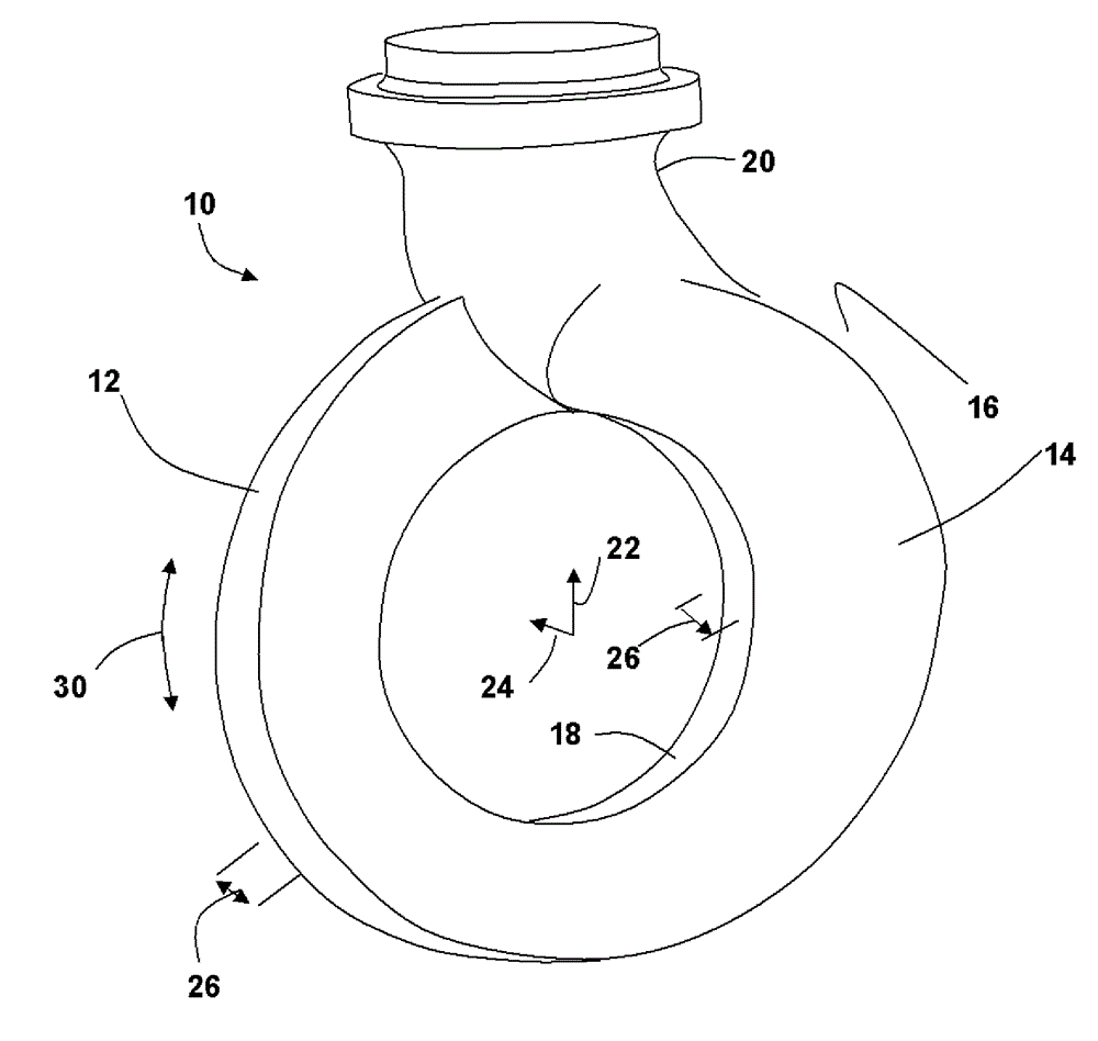
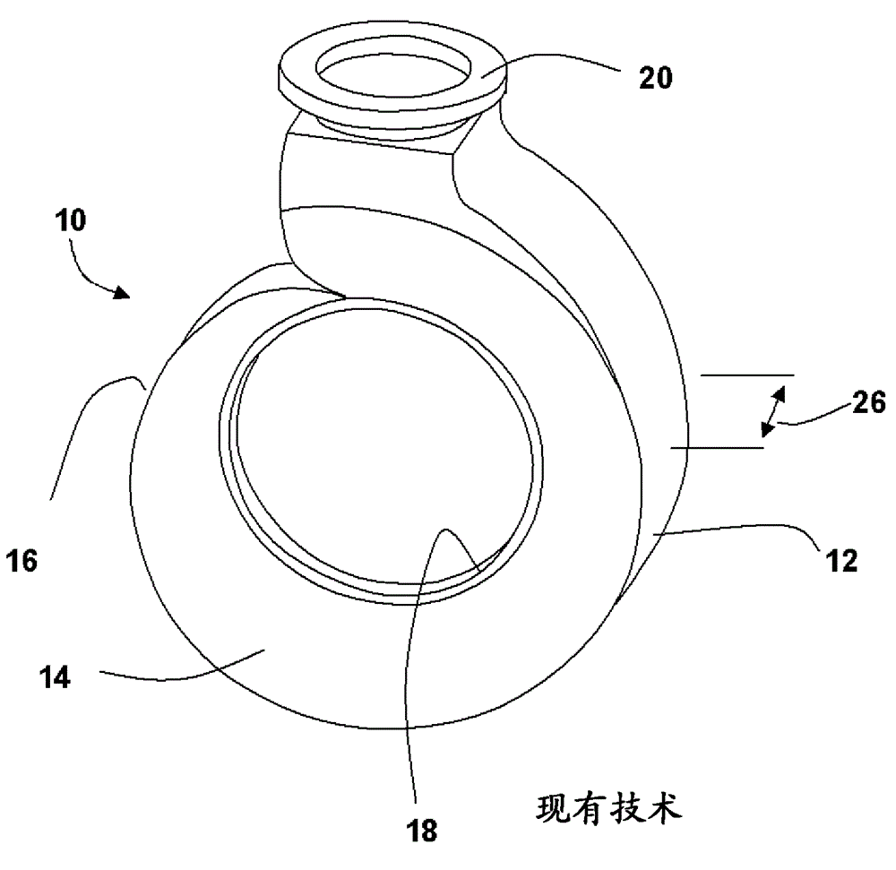
[0023] exist figure 2 The exemplary embodiment shown in is a scroll 10 for a turbomachine comprising an outer wall 12 defining a circular outer radial limit of the scroll 10 and having a constant circumferential diameter.

[0024] exist figure 2 In yet another exemplary embodiment shown in , two end walls 14 , 16 displaced in axial direction 24 extend radially inwards from outer wall 12 in radial direction 22 . The distance between the end walls 14 , 16 in the axial direction 24...


PUM


Abstract

The invention relates to a scroll (10) used for a turbine, and the scroll comprises an outer wall (12). The outer wall (12) defines round external radial limitation of the scroll (10). The scroll (10) is characterized in that the outer wall (12) has constant circumferential diameter. The scroll also comprises end walls (14,16) which can be separated axially, and the end walls (14,16) extend inward from the radial direction of the outer wall (12), to limit an air chamber between the end walls, and a periphery internal opening (20) on the radial internal boundary of the scroll (10). Any one of the first end wall (14) and the second end wall (16) or both of the first end wall (14) and the second end wall (16) can curl, so that on a circumferential direction (28), the first end wall (14) and the second end wall (16) extend from a first point of the outer wall (12) and get back to the first point of the outer wall (12), and the axial width (26) of the outer wall (12) is reduced.

Description

technical field [0001] The present disclosure relates to the arrangement of scrolls in turbomachines. Background technique [0002] It is known in the art relating to turbomachines to provide an inlet duct which changes from an open duct to an annular passage for delivering gas to the inlet of the turbine with relatively equal pressure and flow distribution around the annular inlet of the turbine. In the case of an offset system connection, the inlet pipe can be combined with an annular scroll providing a chamber-like volume to distribute the exhaust gas equally through the angled vanes of the nozzle ring to the energy conversion vanes of the turbine wheel . The equal distribution of exhaust gases to the annular turbine inlet provides the advantage of minimal plenum area where it allows a relatively short axial distance for connecting the exhaust manifold with the laterally offset turbine inlet to the turbine. [0003] exist figure 1 The arrangement of the inlet scroll fo...

Claims


Application Information

Patent Timeline
IPC IPC(8): F01D9/02
Inventor A.C.洛德K.米斯特里
Owner GENERAL ELECTRIC TECH GMBH
Why Eureka
Try Eureka