Cage for inclined ball bearing

Inactive Publication Date: 2016-02-11
SCHAEFFLER TECH AG & CO KG
View PDF2 Cites 1 Cited by
  • Summary
  • Abstract
  • Description
  • Claims
  • Application Information

AI Technical Summary

Benefits of technology

[0020]Rolling ball bearings, in particular inclined ball bearings, which use a cage according to the pr

Problems solved by technology

This takes place at the expense of the stability of the cage and also results in a logistics problem, i.e., the entanglement of the rings which are reinforced only on one side in larger

Method used


Image

  • Cage for inclined ball bearing
  • Cage for inclined ball bearing

Examples


Embodiment Construction

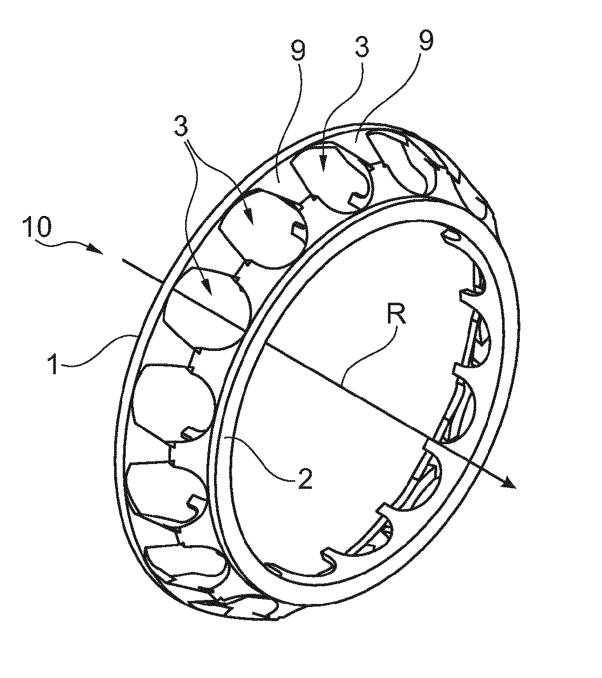
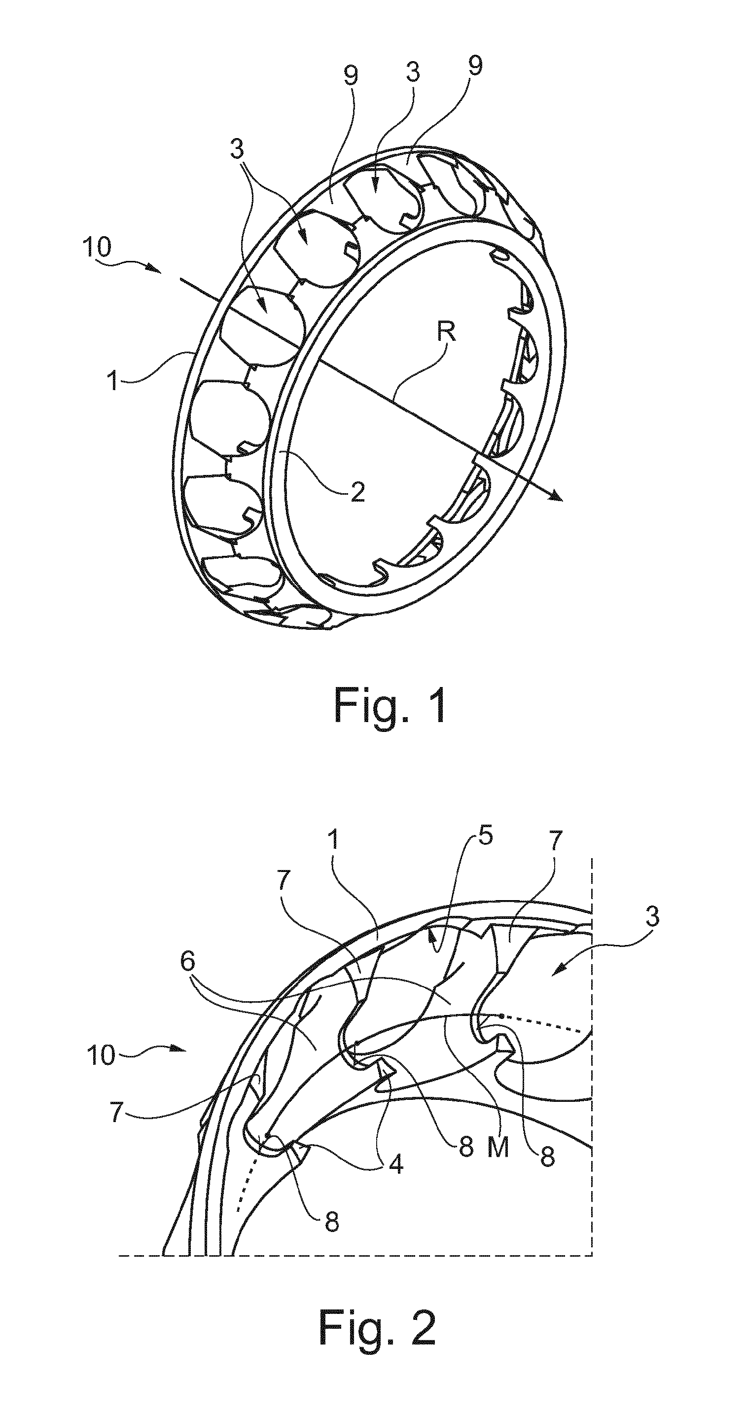
[0025]FIG. 1 shows an inclined ball bearing cage 10 including its axis of rotation R. Ball pockets 3 are separated by webs 9, webs 9 also connecting rings 1, 2 to each other and ensuring a sufficient stability.

[0026]FIG. 2 shows a section of inclined ball bearing cage 10, the areas around bifurcations 8 of three webs 9 being more clearly apparent. Free ends 4, together with first ends 7 of webs 9, form required bifurcation 8. Bifurcations 8 are open in the axial direction, oriented toward first ring 1. This characteristic results in the logistical advantage that cages having identical dimensions may be stacked into each other, second ring 2 of a cage being enclosed in bifurcations 8 of the adjacent cage.

[0027]In addition, the rings are in any case designed in such a way that they are not able to become entangled with each other and are thus easy to separate. This characteristic is based essentially on the design of first ring 1.

[0028]Rolling body pockets 3 largely fit snugly against...


PUM


Abstract

A rolling bearing cage 10 with two rings 1,2 connected by webs 9, wherein webs 9 provided with bifurcations 8 are used to solve the problem of reducing weight while simultaneously ensuring increased load rating, wherein said webs 9 permit adjacent rolling bodies to be arranged very close to one another. Furthermore, a plurality of identical cages 10 are prevented from tangling in each other when said cages are heaped in large quantities. Overall, the cage 10 allows a more compact design for inclined ball bearings and also reduces their moment of friction.

Description

[0001]The present invention relates to a rolling bearing cage for accommodating rolling bodies designed as balls, including two axially opposite rings and webs forming rolling body pockets together with the rings, a first reference circle diameter of the first ring being greater than a second reference circle diameter of the second ring and also being greater than the reference circle diameter of the rolling bodies. In addition, the present invention relates to a rolling bearing, in particular an inclined ball bearing, including one or multiple of these cages.BACKGROUND[0002]Such a rolling body cage is present in most cases in inclined ball bearings, for example, in double-row inclined ball bearings. The rolling bearing cage has the task of spacing the ball-shaped rolling bodies situated and guided in it in such a way that a high load rating is possible due to an optimal filling.[0003]Today, inclined ball bearings are, for example, designed to include window cages or snap cages. The...

Claims


Application Information

Patent Timeline
IPC IPC(8): F16C33/38F16C19/16
CPCF16C19/163F16C33/3862F16C33/3856F16C33/3887F16C2326/02F16C33/3843F16C19/16F16C33/38
Inventor HEISS, RALFEICHELMANN, FRANKGESSNER, FELIX
Owner SCHAEFFLER TECH AG & CO KG
Why Eureka
Try Eureka