
Damping ring for large overhanging boring cutter rod and application method

A technology of boring bar and damping ring, which is applied in the field of machining tools, can solve the problems of complex structure of the supporter, increase of production cost, lack of versatility, etc., and achieve stable and reliable overall structure, firm and reliable use, and optimal reduction The effect of the vibration effect

Active Publication Date: 2018-10-12
SHANDONG UNIV
View PDF11 Cites 1 Cited by
  • Summary
  • Abstract
  • Description
  • Claims
  • Application Information

AI Technical Summary

Problems solved by technology

However, the structure of the support is complex, there are many parts, and the installation is cumbersome, and it can only be applied to a specific size of the tool holder, which does not have good versatility, which also increases the production cost
[0008] To sum up, in the prior art, there is still no effective solution to the vibration problem in the process of using a large overhang boring bar for machining

Method used


Image

  • Damping ring for large overhanging boring cutter rod and application method
  • Damping ring for large overhanging boring cutter rod and application method
  • Damping ring for large overhanging boring cutter rod and application method

Examples


Embodiment Construction

[0042] It should be pointed out that the following detailed description is exemplary and intended to provide further explanation to the present application. Unless defined otherwise, all technical and scientific terms used herein have the same meaning as commonly understood by one of ordinary skill in the art to which this application belongs.

[0043] It should be noted that the terminology used here is only for describing specific implementations, and is not intended to limit the exemplary implementations according to the present application. As used herein, unless the context clearly dictates otherwise, the singular is intended to include the plural, and it should also be understood that when the terms "comprising" and / or "comprising" are used in this specification, they mean There are features, steps, operations, means, components and / or combinations thereof.

[0044] For the convenience of description, if the words "up", "down", "left" and "right" appear in the present i...


PUM


Abstract

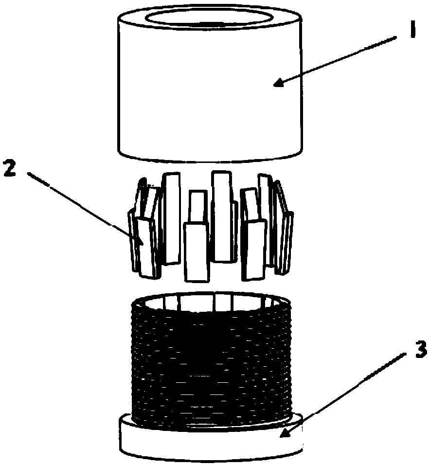
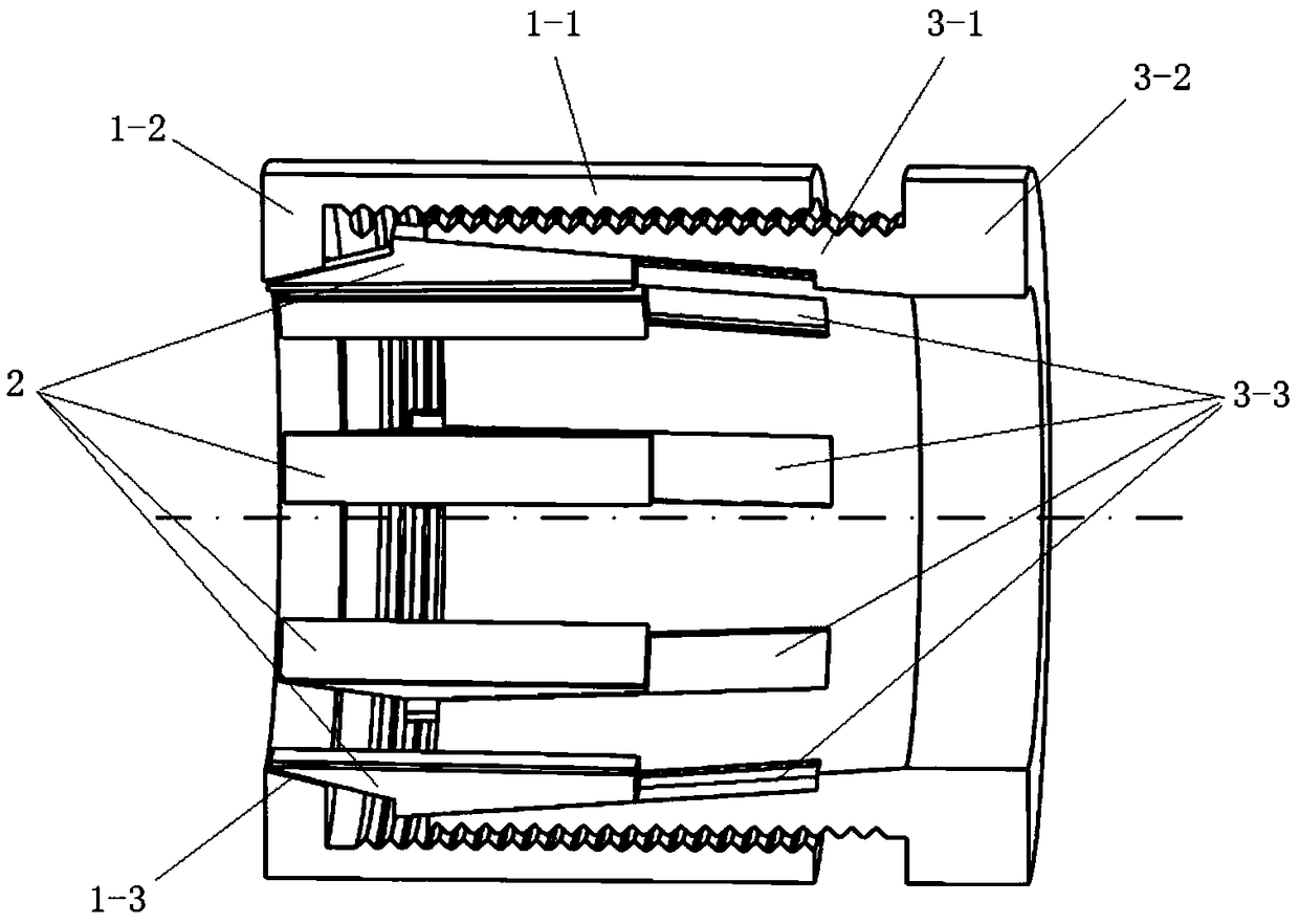
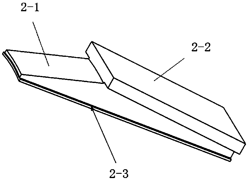
The invention relates to a damping ring for a large overhanging boring cutter rod and an application method. The damping ring comprises an annular base, an annular top sleeve and clamping bodies; thebase is in threaded connection with the top sleeve; chutes, uniformly distributed at the periphery of the base and inclined to the axis of the base, are arranged on the inner surface of the base; an ejecting surface, inclined to the axis of the top sleeve, is arranged on the inner surface of the top sleeve; the clamping bodies are provided with ejecting parts and sliding parts; the ejecting partsare provided with first inclined surfaces contacted with the ejecting surface; the sliding parts are provided with second inclined surfaces contacted with the bottom surfaces of the chutes; the top sleeve is rotated, and moves in the axial direction of the base through threaded connection; the ejecting surface pushes the clamping bodies through the first inclined surfaces; the clamping bodies aredriven to move in the chutes through the second inclined surfaces; and the radius of the periphery of the multiple clamping bodies is reduced to clamp the cutter rod. The damping ring is simple in structure, convenient to use and excellent in damping effect.

Description

technical field [0001] The invention relates to the technical field of cutting tools for machining, in particular to a vibration damping ring for a large-overhang boring bar and a use method thereof. Background technique [0002] In metal cutting, the tool bar is prone to bending deformation under the action of cutting force. When the length-to-diameter ratio (L / D) of the tool bar is greater than 4, the tool bar itself will vibrate, which will affect the processing or even cause the processing to be impossible. Due to the limitation of the machining size of the workpiece, it is unrealistic to suppress the vibration by shortening the overhang length of the tool bar and increasing the parameter of the tool bar diameter. Reducing the cutting thickness will inevitably lead to a reduction in cutting efficiency. Although the material with a large elastic modulus is used for the tool bar to increase the static stiffness of the tool bar and reduce the bending deformation, the vibra...

Claims


Application Information

Patent Timeline
Patent Type & Authority Applications(China)
IPC IPC(8): B23B29/02B23Q11/00
CPCB23B29/022B23Q11/0032Y02P70/10
Inventor 宋清华王抒予刘战强高建王兵万熠
Owner SHANDONG UNIV
Learn More