
Method, compressor and turbomachine

a compressor and turbomachine technology, applied in the field of methods, compressors and turbomachines, can solve the problems of stability and efficiency limitations, high load on the rear stages, etc., and achieve the effect of high efficiency and high stability

Active Publication Date: 2019-07-02
MTU AERO ENGINES GMBH
View PDF36 Cites 0 Cited by
  • Summary
  • Abstract
  • Description
  • Claims
  • Application Information

AI Technical Summary

Benefits of technology

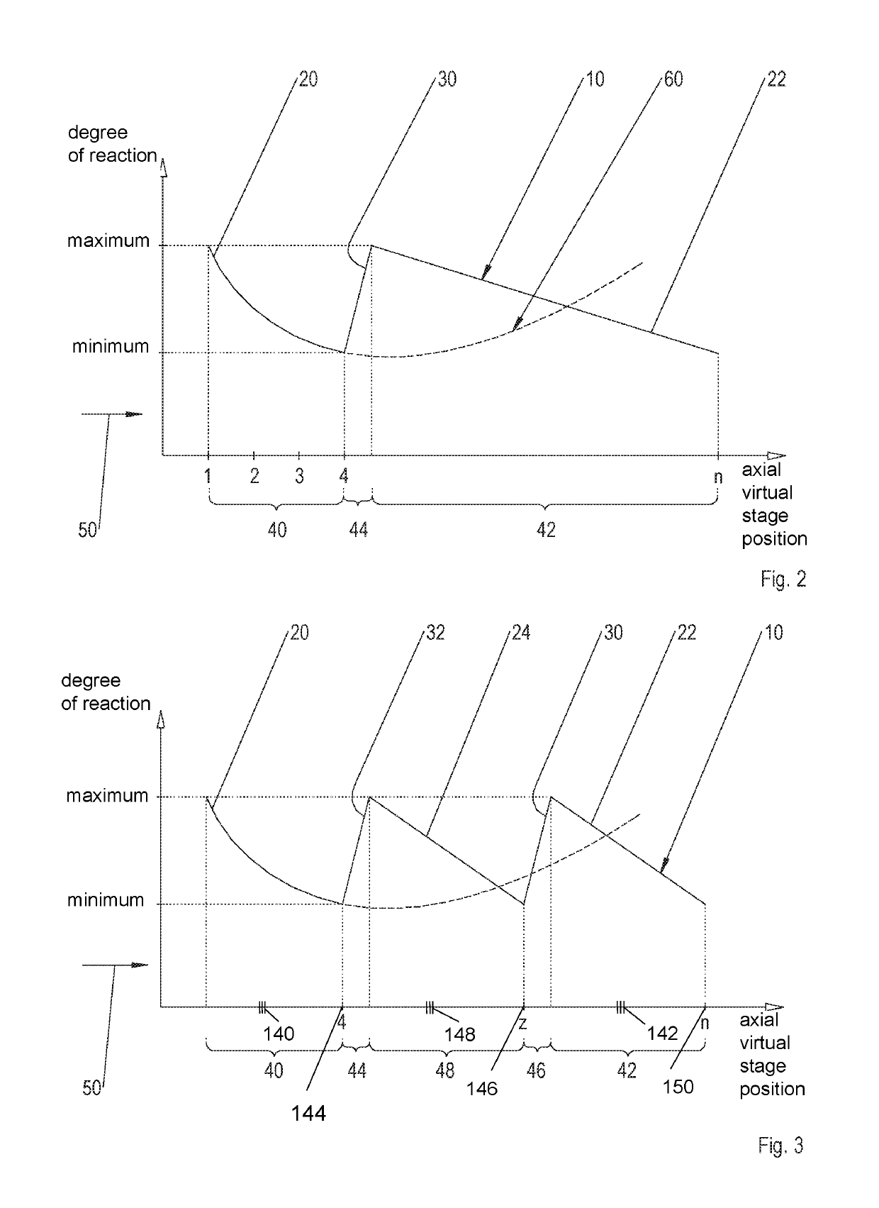
This approach enhances stability and efficiency by reducing the load on rear guide baffles, minimizing losses, and ensuring a swirl-free main flow to the combustion chamber, particularly beneficial in long compressors or those with many stages, while maintaining high stability and efficiency across multiple stages.

Problems solved by technology

Due to the rise, a residual swirl in the main flow may be reduced in the rear compressor area and in particular at the outlet guide baffle of the compressor; however, the rise causes a high load on the rear stages, which results in stability and efficiency limitations.

Method used


Image

  • Method, compressor and turbomachine
  • Method, compressor and turbomachine

Examples


Embodiment Construction

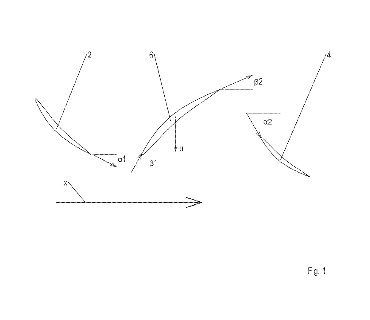
[0024]As already mentioned at the outset, a compressor-side degree of reaction of a turbomachine in the context of the present invention is calculated, in a simplified way, according to the following formula, based on metal angles:

[0025]R=tan⁢⁢β⁢⁢1+β22tan⁢⁢β1+β22+tan⁢⁢α1+α22

[0026]The angles α1, α2, β1, β2 are, as shown in FIG. 1, are marked between tangents of the respective camber line and an axial flow direction x of the turbomachine. α1 is marked from the trailing edge of a guide blade 2 of a row of guide blades n−1. α2 is marked toward the leading edge of a guide blade 4 of a row of guide blades n. 131 is marked toward the leading edge of a moving blade 6 of a row of moving blades n. 132 is marked from the trailing edge of moving blade 6 of a row of moving blades n. Moving blade 6 or row of moving blades n thereby passes through between guide blades 2, 4 or rows of guide blades n−1, n in the circumferential direction u. Letter n designates whole number multiples of 1, 2, etc. In...


PUM


Abstract

Disclosed is a method for operating a compressor of a turbomachine, in which, when viewed in the direction of a main flow, a slowly dropping degree of reaction being raised in one compressor area more quickly than previously dropped and the raised degree of reaction then being reduced again in a subsequent compressor area more slowly that it was previously raised, a compressor of a turbomachine including at least one degree of reaction rising more quickly in one compressor area in comparison to adjacent compressor areas with respectively a dropping degree of reaction, whereby a sawtooth-shaped curve of the degree of reaction results, and a turbomachine including a compressor of this type.

Description

[0001]This claims the benefit of German Patent Application DE 10 2015 223 212.3, filed Nov. 24, 2015 and hereby incorporated by reference herein.[0002]The invention relates to a method for operating a compressor of a turbomachine, a compressor of a turbomachine, and a turbomachine.BACKGROUND[0003]In conventional axial compressors of turbomachines, such as aircraft engines and static gas turbines, a degree of reaction in the front compressor area drops from an inlet-side maximum to a minimum. The degree of reaction may be calculated in a simplified way according to the following formula, based on metal angles:[0004]R=tan⁢⁢β⁢⁢1+β22tan⁢⁢β1+β22+tan⁢⁢α1+α22[0005]The angles α1, α2, β1, β2 are, as shown in FIG. 1, marked between tangents of the respective camber line and an axial flow direction x of the turbomachine. α1 is marked from the trailing edge of a guide blade 2 of a row of guide blades n−1. α2 is marked toward the leading edge of a guide blade 4 of a row of guide blades n. β1 is ...

Claims


Application Information

Patent Timeline
Patent Type & Authority Patents(United States)
IPC IPC(8): F04D19/00F04D29/32F04D29/56F04D29/54F04D27/00F04D19/02F01D5/14
CPCF04D27/002F01D5/146F04D19/00F04D29/563F04D29/324F04D29/541F04D19/02F04D29/542Y02T50/60
Inventor ELORZA GOMEZ, SERGIOSCHNEIDER, TIM
Owner MTU AERO ENGINES GMBH
Learn More