Method, compressor and turbomachine

Active Publication Date: 2017-05-25
MTU AERO ENGINES GMBH
View PDF0 Cites 0 Cited by
  • Summary
  • Abstract
  • Description
  • Claims
  • Application Information

AI Technical Summary

Benefits of technology

The present invention provides a method for operating a compressor of a turbomachine in a way that improves stability and efficiency. The method involves raising the degree of reaction quickly in one compressor area and then reducing it slowly again, which results in a high degree of reaction that indicates a high stability and low sensitivity. This is particularly beneficial at a partial load and helps prevent pumping. Additionally, this method allows for a reduction in the number of blades or a smaller axial width of the compressor, resulting in decreased losses and improved efficiency. The method also helps achieve a favorable incident flow of a combustion chamber area by decreasing swirl in the main flow after the speed of reaction has slowed down.

Problems solved by technology

Due to the rise, a residual swirl in the main flow may be reduced in the rear compressor area and in particular at the outlet guide baffle of the compressor; however, the rise causes a high load on the rear stages, which results in stability and efficiency limitations.

Method used


Image

  • Method, compressor and turbomachine
  • Method, compressor and turbomachine
  • Method, compressor and turbomachine

Examples


Embodiment Construction

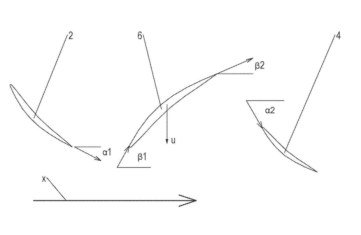
[0023]As already mentioned at the outset, a compressor-side degree of reaction of a turbomachine in the context of the present invention is calculated, in a simplified way, according to the following formula, based on metal angles:

R=tanβ1+β22tanβ1+β22+tanα1+α22

[0024]The angles α1, α2, β1, β2 are, as shown in FIG. 1, are marked between tangents of the respective camber line and an axial flow direction x of the turbomachine. α1 is marked from the trailing edge of a guide blade 2 of a row of guide blades n−1. α2 is marked toward the leading edge of a guide blade 4 of a row of guide blades n. 131 is marked toward the leading edge of a moving blade 6 of a row of moving blades n. 132 is marked from the trailing edge of moving blade 6 of a row of moving blades n. Moving blade 6 or row of moving blades n thereby passes through between guide blades 2, 4 or rows of guide blades n−1, n in the circumferential direction u. Letter n designates whole number multiples of 1, 2, etc. In compressors, ...


PUM


Abstract

Disclosed is a method for operating a compressor of a turbomachine, in which, when viewed in the direction of a main flow, a slowly dropping degree of reaction being raised in one compressor area more quickly than previously dropped and the raised degree of reaction then being reduced again in a subsequent compressor area more slowly that it was previously raised, a compressor of a turbomachine including at least one degree of reaction rising more quickly in one compressor area in comparison to adjacent compressor areas with respectively a dropping degree of reaction, whereby a sawtooth-shaped curve of the degree of reaction results, and a turbomachine including a compressor of this type.

Description

[0001]This claims the benefit of German Patent Application DE 10 2015 223 212.3, filed Nov. 24, 2015 and hereby incorporated by reference herein.[0002]The invention relates to a method for operating a compressor of a turbomachine, a compressor of a turbomachine, and a turbomachine.BACKGROUND[0003]In conventional axial compressors of turbomachines, such as aircraft engines and static gas turbines, a degree of reaction in the front compressor area drops from an inlet-side maximum to a minimum. The degree of reaction may be calculated in a simplified way according to the following formula, based on metal angles:R=tanβ1+β22tanβ1+β22+tanα1+α22[0004]The angles α1, α2, β1, β2 are, as shown in FIG. 1, marked between tangents of the respective camber line and an axial flow direction x of the turbomachine. α1 is marked from the trailing edge of a guide blade 2 of a row of guide blades n−1. α2 is marked toward the leading edge of a guide blade 4 of a row of guide blades n. β1 is marked toward ...

Claims


Application Information

Patent Timeline
IPC IPC(8): F04D27/00F04D29/54F04D29/56F04D19/00
CPCF04D27/002F04D29/563F04D29/541F04D19/00F01D5/146F04D19/02F04D29/324F04D29/542Y02T50/60
Inventor ELORZA GOMEZ, SERGIOSCHNEIDER, TIM
Owner MTU AERO ENGINES GMBH
Why Eureka
Try Eureka