Process reactor and method for the electrodynamic fragmentation

Inactive Publication Date: 2006-07-27
KERNFORSCHUNGSZENTRUM KARLSRUHE GMBH
View PDF9 Cites 11 Cited by
  • Summary
  • Abstract
  • Description
  • Claims
  • Application Information

AI Technical Summary

Benefits of technology

[0029] First, the material flow in the process space would be detrimentally affected by an overload of material volume. During treatment by exposure to the shockwaves, the material cannot freely move around with each pulse so that the fragmentation is less uniform.
[0030] Second, it has been found that the excessive charge of the reaction space with added material causes the formation of cavities, that is, a so-called silo-effect. By forming a stable vault ceiling, these cavities at times have such a high stability that the material transport is completely inhibited.
[0031] The average residence time of the material to be fragmented is controlled

Problems solved by technology

For industrially relevant throughputs a batch-mode however is not particularly suitable.
The apparatus disclosed in [2] is for a continuous supply of material but, because of the sieve used, it is not suitable for relatively large mass-throughputs.
U.S. Pat. No. 6,039,274 (FIG. 1) also discloses a continuous material flow in connection with a sieve or, respectively, a vibration sieve; however, there are unsolved points, that is, the throughput, the treatment duration and the life of the sieve.
Generally, it can be said that an important weak point of all apparatus concerns the sieve bottom in the process chamber which allows only a relatively small throughput volume and the largest added component which is allowed to leave the process area is always smaller than the mesh width of the sieve.
This effect however is not desirable if, in addition to the basic requirement for fragmentation, the components should maintain a certain size which, in a heterogeneous material, may play

Method used


Image

  • Process reactor and method for the electrodynamic fragmentation
  • Process reactor and method for the electrodynamic fragmentation

Examples


Example

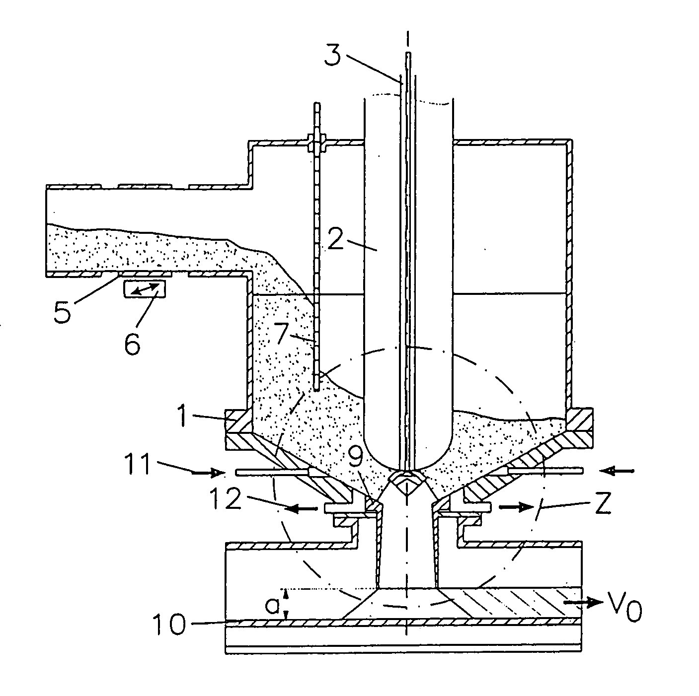
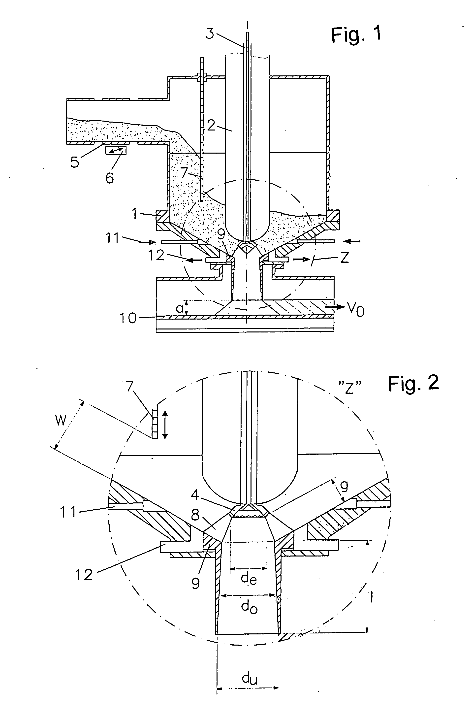
[0046] The material to be fragmented is moved by vibration via the movably supported tube 5, that is a jarring structure, from the material receiving funnel into the barrel-like reaction chamber 1 of sheet metal. The amount of the material supplied is adjustable by the intensity of the vibration or jarring drive 6. In order to avoid excessive filling of the reaction chamber 1, but also to protect the high voltage electrode 3 and the isolator 2 thereof, a baffle 7 is installed in the reaction chamber in a height-adjustable manner. With the adjustable passage way w between the lower edge of the baffle 7 and the funnel-shaped wall of the reaction chamber 1, the height of the filling of the material to be processed in the reaction chamber above the reaction zone 8 is limited independently of the action of the jarring device 6 of the material transport. As a result, the residence time of the material before processing is reduced. The limitation of the overall amount of material in the re...


PUM


Abstract

In a process reactor and a method for the electro-dynamic fragmentation of lumpy mineral materials by pulsed high voltage discharges, including a reaction chamber with a funnel-like bottom having a central outlet, an axially movable high-voltage electrode extending from the top into the reaction chamber and having a front end disposed opposite the central outlet where another electrode which is at an electric reference potential is disposed, the outlet converges into a tailback tube below which a transport unit for the controlled removal of the processed fragmented material sinking down through the tailback tube is disposed, a material supply arrangement extends to an opening in the wall of the reaction chamber and a material flow blocking structure is disposed in the reaction in front of the material inlet opening for controlling the material admission to, and the fill level in, the reaction chamber.

Description

[0001] This is a continuation-in-part application of international patent application PCT / EP2004 / 008802 filed Aug. 06, 2004 and claiming the priority of German patent application 103 46 650.9 filed Oct. 03, 2003. BACKGROUND OF THE INVENTION [0002] The invention relates to a process reactor for the electro-dynamic fragmentation of particulate mineral materials immersed in a processing fluid by pulsed high-voltage discharges and a method for operating the process reactor. [0003] In its basic design, such a process reactor comprises: A closed reaction chamber with a funnel-like bottom including a central outlet. An electrode to which a high voltage can be applied, that is a high voltage electrode, extends from the top into the reaction chamber. This electrode is surrounded by an electrical insulation except for a free end area thereof. The high voltage electrode is movable along the axis thereof so that its end is disposed opposite the central outlet at the funnel-like bottom of the re...

Claims


Application Information

Patent Timeline
IPC IPC(8): B02C19/00B02C19/18
CPCB02C19/18B02C2019/183
Inventor HOPPE, PETERSINGER, JOSEFGIESE, HARALDSTEMMERMANN, PETERSCHWEIKE, UWEEDINGER, WOLFRAM
Owner KERNFORSCHUNGSZENTRUM KARLSRUHE GMBH
Why Eureka
Try Eureka