Crop harvester having metal conditioner rolls with herringbone rib pattern

a harvester and metal conditioner technology, applied in the direction of mowers, agriculture tools and machines, agriculture, etc., to achieve the effect of improving crop conditioning, uniform distribution, and concentrating the action even more aggressiv

Active Publication Date: 2011-08-30
AGCO CORP
View PDF26 Cites 13 Cited by
  • Summary
  • Abstract
  • Description
  • Claims
  • Application Information

AI Technical Summary

Benefits of technology

[0002]Conditioning rolls with helical ribs or bars extending in a continuous spiral from one end of the roll to the other have a tendency to load up crop materials along one side of the conditioned crop discharge flow from the rolls. Consequently, the resulting windrows or swaths may be less uniform than desired, with heavier accumulations along one side than the other. This can have an adverse effect upon drying times and hay quality. Moreover, in many harvesters the cutting swath is wider than the centrally disposed inlet opening to the conditioning rolls such that outboard severed materials must be gathered centrally by augers or other means before they can enter the inlet. This increases the likelihood that the discharge flow will have heavier accumulations of materials along its sides than in the middle, in contrast to the desired goal of having the flow as uniform as possible across its entire width.
[0003]The present invention provides a novel method and apparatus for obtaining improved crop conditioning. In its broadest aspects it involves the discovery that significantly more uniform distribution can be obtained when the rib pattern is herringbone-shaped, rather than a continuous spiral, and the rolls are constructed from a hard, non-compressible material, such as steel. The herringbone pattern naturally tends to draw the outer materials toward the center of the rolls when the pattern is properly oriented with respect to the direction of roll rotation, and the hard, metal nature of the ribs makes their centering action even more aggressive than would otherwise be the case. This is especially beneficial in harvesters using rotary cutters as the means for severing the standing crop from the ground as these machines tend to run faster and present higher quantities of materials to the rolls in less time than sickle-type machines, presenting an even greater challenge to uniform distribution within the windrow or swath.
[0004]In another aspect the present invention contemplates passing the severed materials through dual sets of conditioning rolls wherein both front and rear pairs of the rolls are constructed from metal and have herringbone rib patterns, providing an extra level of conditioning coupled with speed and uniformity that has particular utility for rotary cutoff machines. For sickle-type machines, it may be appropriate to use metal, herringbone rolls at the front and compressive-surface herringbone rolls at the rear.

Problems solved by technology

Because rotary machines typically run at faster ground speeds than sickle machines, they present larger volumes amounts of crop materials to the conditioning rolls per unit of time, creating a challenge to proper and effective conditioning.

Method used


Image

  • Crop harvester having metal conditioner rolls with herringbone rib pattern
  • Crop harvester having metal conditioner rolls with herringbone rib pattern
  • Crop harvester having metal conditioner rolls with herringbone rib pattern

Examples


Embodiment Construction

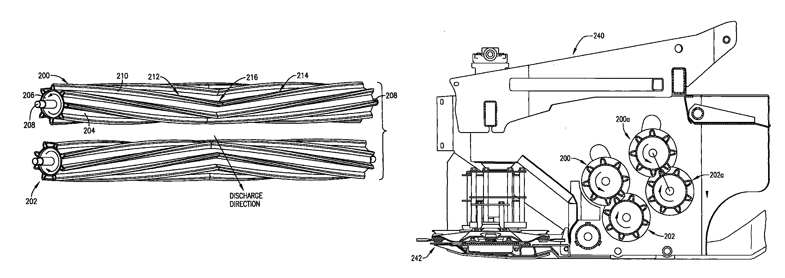
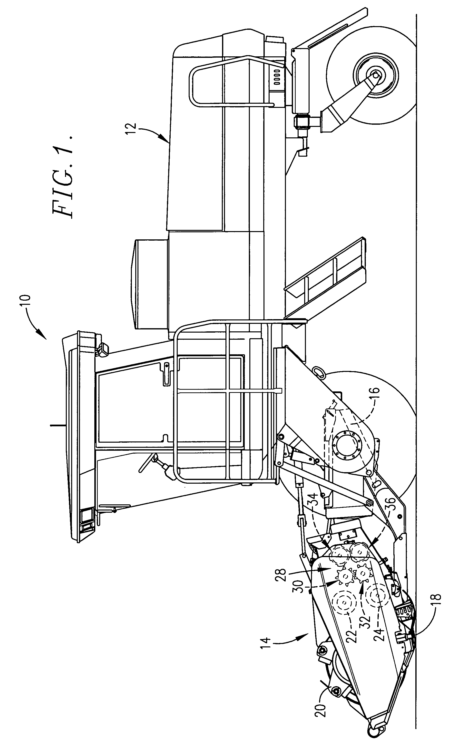
[0020]The present invention is susceptible of embodiment in many different forms. While the drawings illustrate and the specification describes certain preferred embodiments of the invention, it is to be understood that such disclosure is by way of example only. There is no intent to limit the principles of the present invention to the particular disclosed embodiments. For example, the present invention has been illustrated in connection with a self-propelled harvester. However, it will be appreciated that the principles of the present invention may readily be incorporated into a pull-type machine and / or a machine that does not severe crop materials from the field but only performs a separate conditioning function.

The Prior Art Machine of FIGS. 1-9

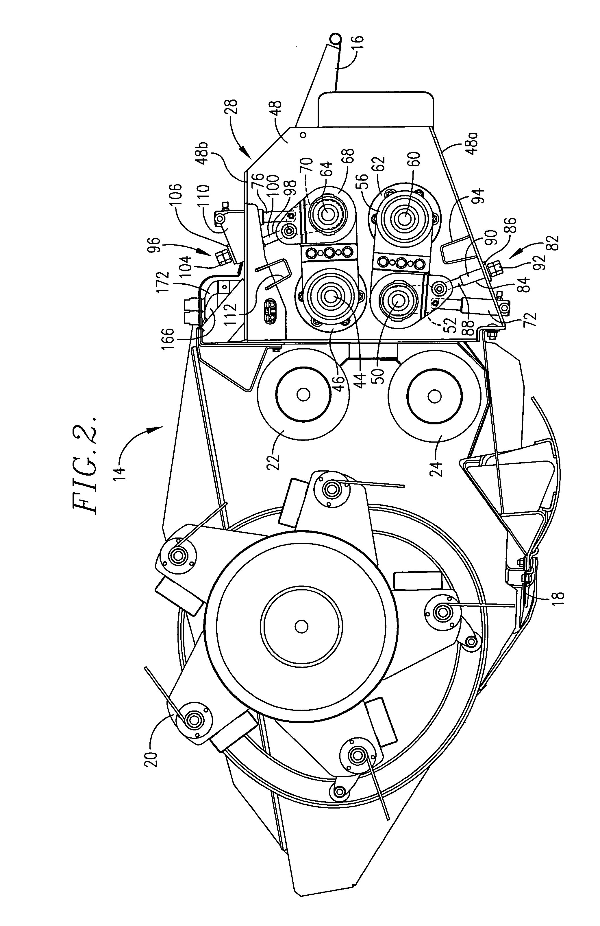
[0021]The machines of the present invention as illustrated in FIGS. 10-15 are similar in many respects to the prior art machine illustrated in FIGS. 1-9. Accordingly, the description which follows initially sets forth details of constructi...


PUM


Abstract

The conditioning rolls of a crop harvester have intermeshing metal ribs arranged in a herringbone pattern, each rib comprising a pair of end-to-end segments that converge spirally from opposite ends of the roll to a centermost apex. Alternative embodiments provide a single pair of metal herringbone rolls, two pairs of metal herringbone rolls, or a front pair of metal herringbone rolls and a rear pair of compressible surface herringbone rolls.

Description

TECHNICAL FIELD[0001]This invention relates to the field of crop harvesting equipment and, more particularly, to a method and apparatus for obtaining conditioned crop materials with improved drying characteristics and more even crop distribution within a windrow or swath.BACKGROUND AND SUMMARY[0002]Conditioning rolls with helical ribs or bars extending in a continuous spiral from one end of the roll to the other have a tendency to load up crop materials along one side of the conditioned crop discharge flow from the rolls. Consequently, the resulting windrows or swaths may be less uniform than desired, with heavier accumulations along one side than the other. This can have an adverse effect upon drying times and hay quality. Moreover, in many harvesters the cutting swath is wider than the centrally disposed inlet opening to the conditioning rolls such that outboard severed materials must be gathered centrally by augers or other means before they can enter the inlet. This increases th...

Claims


Application Information

Patent Timeline
Patent Type & Authority Patents(United States)
IPC IPC(8): A01D61/00
CPCA01D43/10
Inventor PRUITT, MARTIN E.NICKEL, DWIGHT E.GRABER, KURTCLARK, STANLEY R.
Owner AGCO CORP
Why Eureka
Try Eureka