PLL circuit and image display device

Active Publication Date: 2005-02-24
GK BRIDGE 1
View PDF4 Cites 11 Cited by
  • Summary
  • Abstract
  • Description
  • Claims
  • Application Information

AI Technical Summary

Benefits of technology

[0023] The present invention solves the above-mentioned problem of the conventional example and intends to provide a PLL circuit that makes a voltage-controlled oscillato

Problems solved by technology

In the conventional PLL circuit, however, it takes a considerable time for the clock CLK output from the VCO 100 to be stabilized after one extension of the period of the reference input signal HD.
For that reason, the top curl phenomenon in which an upper part of the

Method used


Image

  • PLL circuit and image display device
  • PLL circuit and image display device
  • PLL circuit and image display device

Examples


Example

[0042] Embodiment that specifically describes best modes for conducting the present invention will be described referring to figures below.

[0043]>

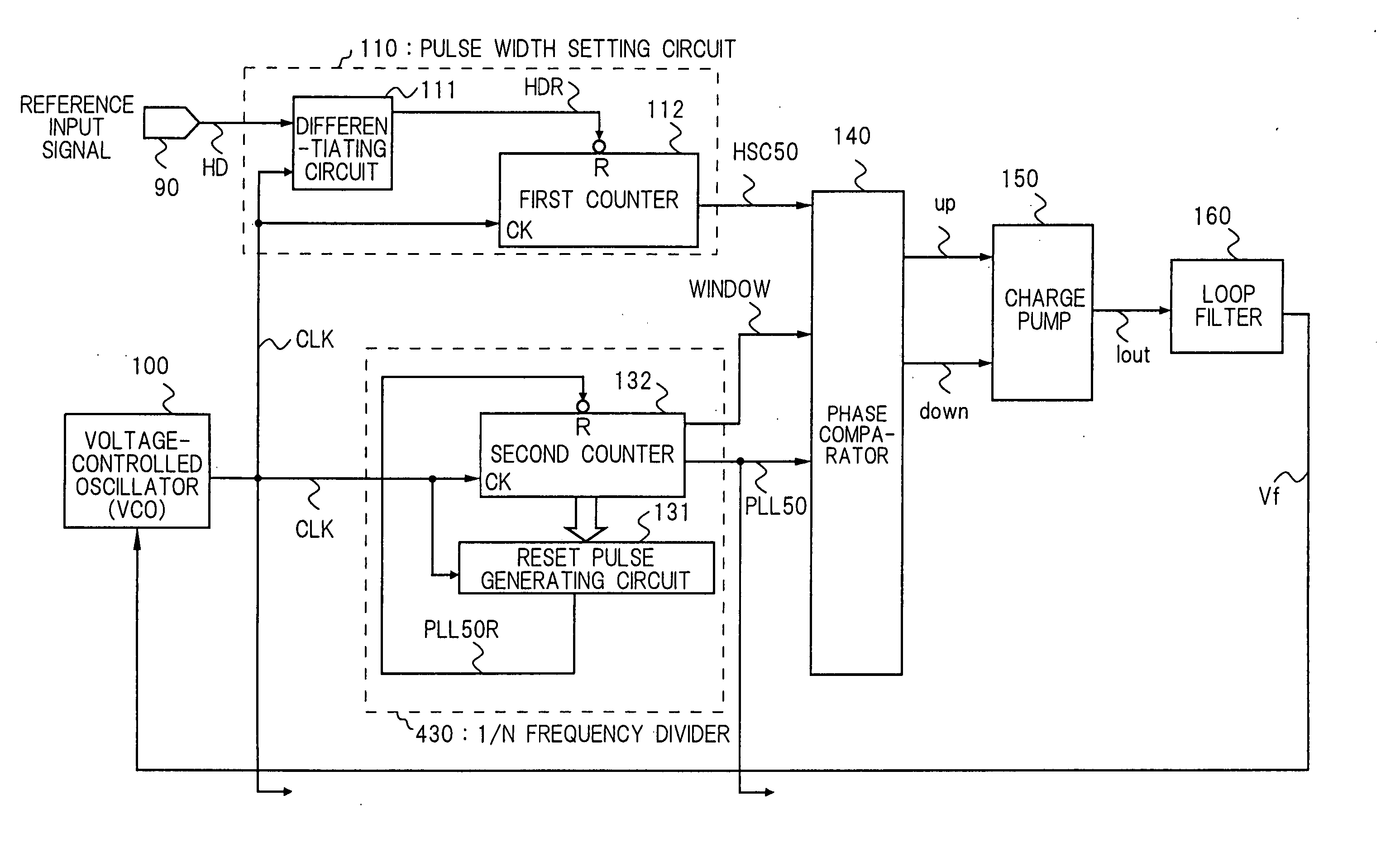
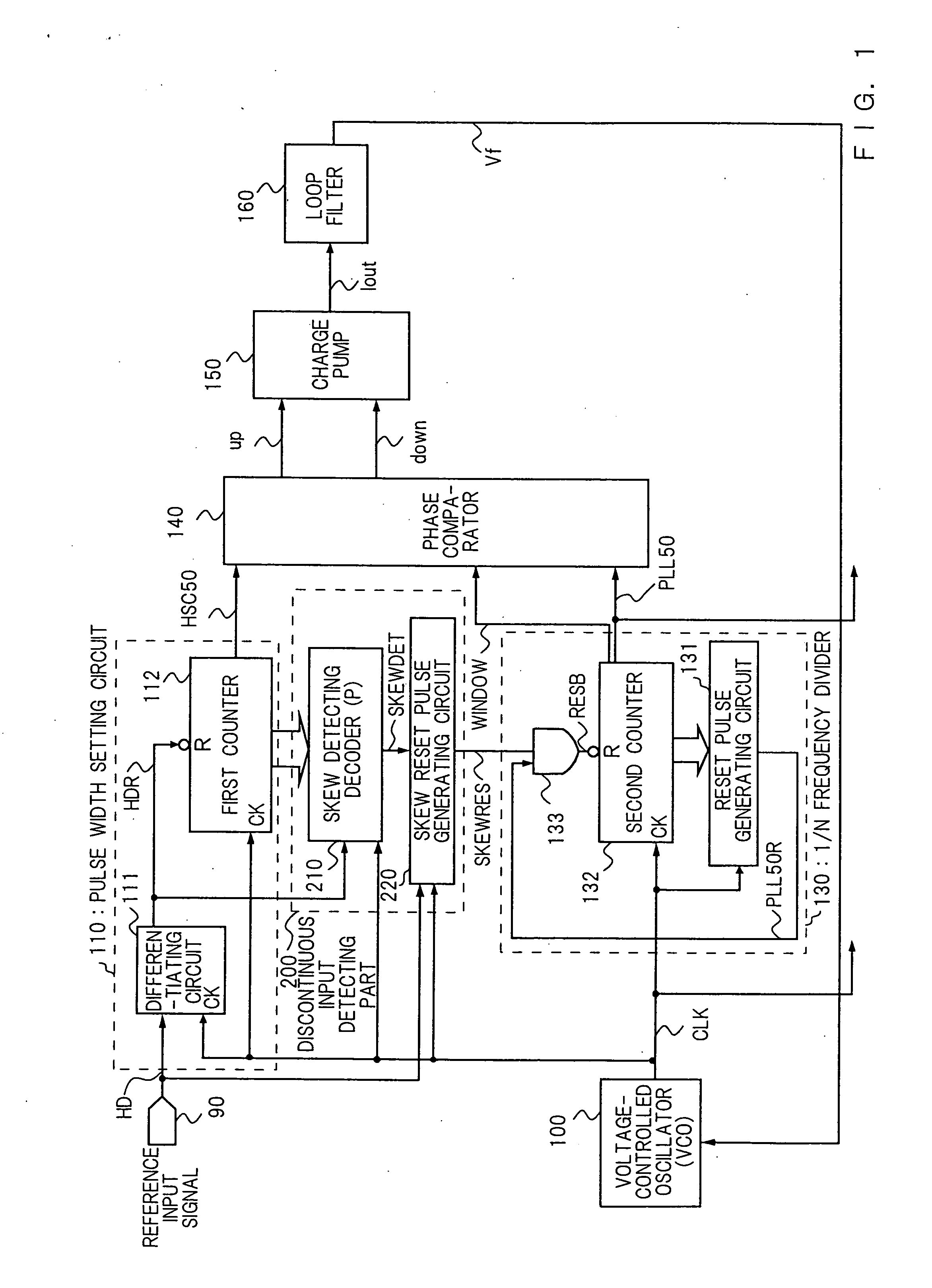
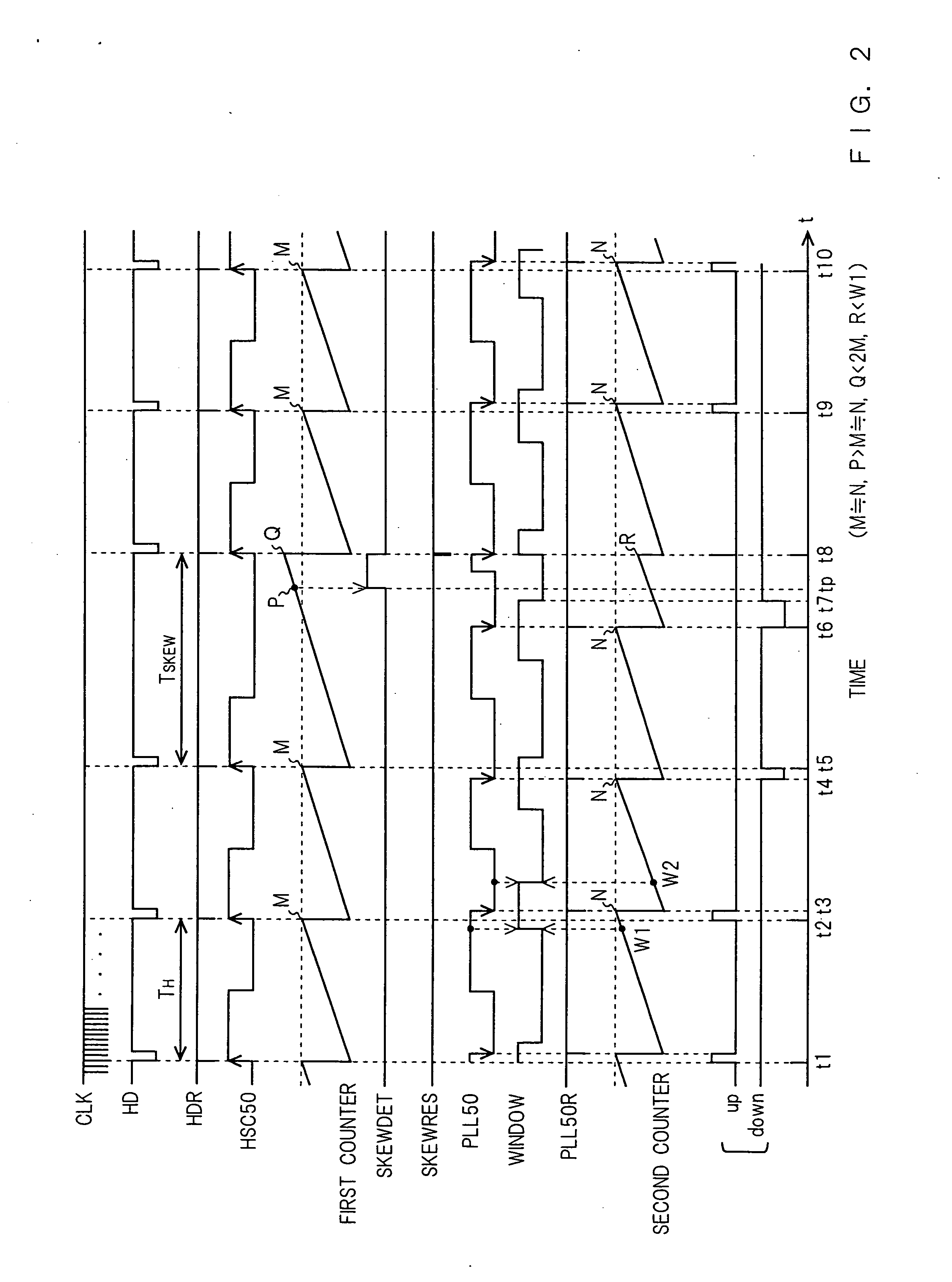
[0044] Referring to FIGS. 1, 2 and 3, a PLL circuit in accordance with an embodiment of the present invention will be described. FIG. 1 is a schematic diagram of the PLL circuit in accordance with the embodiment of the present invention. The PLL circuit of the embodiment has a reference input signal input terminal 90, a pulse width setting circuit 110, a phase comparator 140, a charge pump 150, a loop filter 160, a voltage-controlled oscillator (VCO) 100, a 1 / N frequency divider 130 and a discontinuous input detecting part 200. The pulse width setting circuit 110 has a differentiating circuit 111 and a first counter 112. The 1 / N frequency divider 130 has a second counter 132, a reset pulse generating circuit 131 and an AND gate circuit 133 (LOW logic OR circuit). The discontinuous input detecting part 200 has a skew detecting decoder 210 ...


PUM


Abstract

The present invention provides a PLL circuit that makes a voltage-controlled oscillator converge to a stable state within a short time and generates a clock signal with high stability even when discontinuity occurs in the period of a reference input signal. The PLL circuit of the present invention has a voltage-controlled oscillator for outputting a clock controlled, a first counter reset by the reference input signal having one period longer than a reference period within a predetermined period for outputting a first signal, a second counter for outputting a second signal, a reset pulse generating circuit for resetting the second counter, a loop filter for holding and outputting the control voltage varied by a phase error signal and a discontinuous input detecting part for detecting the reference input signal input initially after its period becomes longer than the reference period.

Description

BACKGROUND OF THE INVENTION [0001] The present invention relates to a PLL (Phase Locked Loop) circuit and an image display device. [0002] The PLL circuit is operated so as to obtain an oscillatory frequency acquired by multiplying the frequency of a reference input signal by N as an output signal of a voltage-controlled oscillator (hereinafter referred to as “VCO”) and match the phase of the reference input signal to that of 1 / N dividing signal (N is an arbitrary positive integer) of the VCO output signal. The PLL circuit is widely used in the analog circuit / digital circuit mixed system such as digital consumer electronics products. [0003] Referring to FIG. 5 and FIG. 6, a conventional PLL circuit will be described. FIG. 5 is a schematic diagram of the conventional PLL circuit. The conventional PLL circuit has a reference input signal input terminal 90, a pulse width setting circuit 110, a phase comparator 140, a charge pump 150, a loop filter 160, a voltage-controlled oscillator (V...

Claims


Application Information

Patent Timeline
IPC IPC(8): H04N5/06H03L7/08H03L7/14H03L7/18
CPCH03L7/1803H03L7/18
Inventor KINUGASA, NORIHIDENIRASAWA, YOSHIOHAMAGUCHI, HIDEOOTA, SACHI
Owner GK BRIDGE 1
Why Eureka
Try Eureka