
Wire arrangement device of moving cone beam CT

A cable arrangement and flat panel technology, applied in the field of mobile CT, can solve the problems of bloating the whole machine, pulling, and increasing the width of the scanning disk, so as to avoid cable entanglement, work safely and reliably, and reduce the axial width.

Pending Publication Date: 2019-03-01
天津金曦医疗设备有限公司
View PDF0 Cites 0 Cited by
  • Summary
  • Abstract
  • Description
  • Claims
  • Application Information

AI Technical Summary

Problems solved by technology

Different from spiral CT axially moving and continuously rotating scanning, cone beam CT is generally driven by a synchronous belt, and only needs to rotate and scan 360-degree effective data to reconstruct and obtain multiple tomographic images. If the power supply and communication methods use carbon brushes and The low-voltage slip ring technology is too costly and has a waste of functions. If a rotary drag chain is installed on the end face of the synchronous pulley on the back side of the scanning disk, the width of the scanning disk will be greatly increased, and the whole machine will appear bloated.
Although other overly complex wiring methods can meet the requirements of power supply and communication, there are safety hazards such as scattered, pulled, and twisted cables, and the actual effect is not ideal

Method used


Image

  • Wire arrangement device of moving cone beam CT
  • Wire arrangement device of moving cone beam CT
  • Wire arrangement device of moving cone beam CT

Examples


Embodiment Construction

[0028] The present invention will be further described below in combination with specific embodiments.

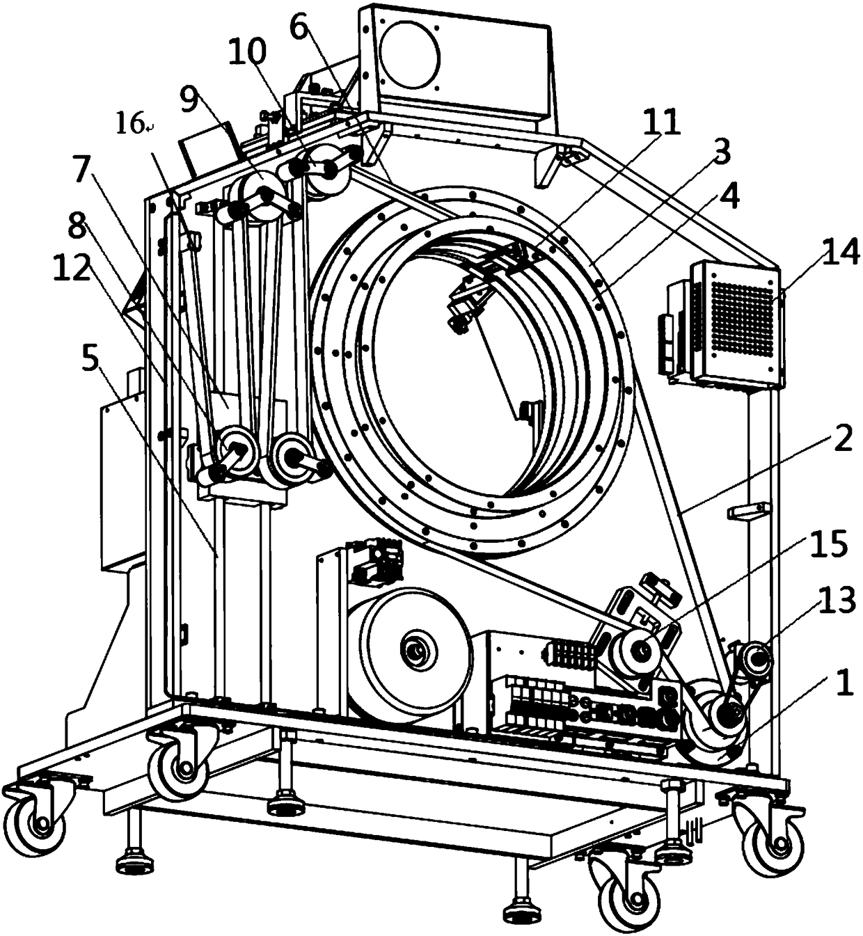
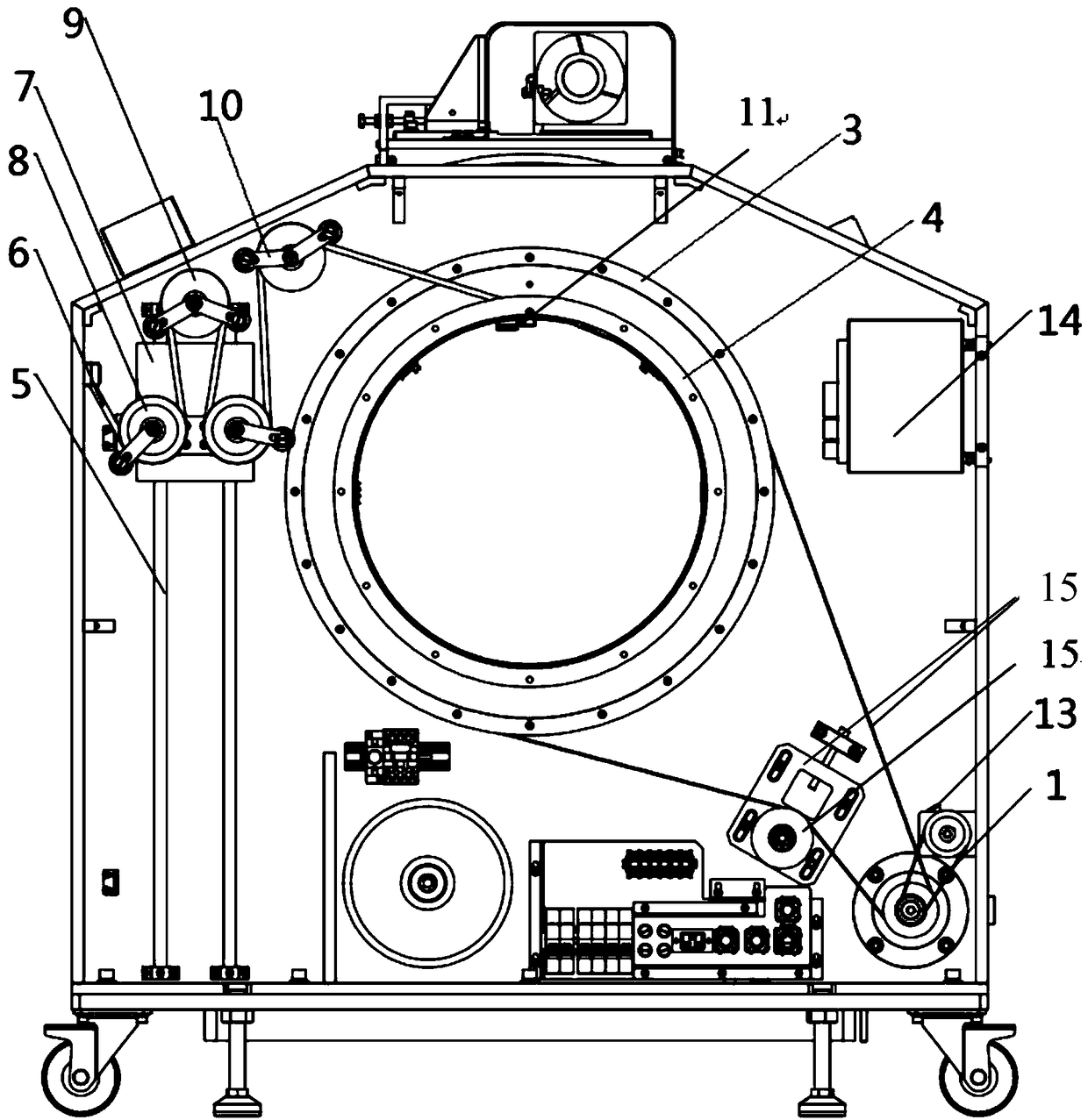
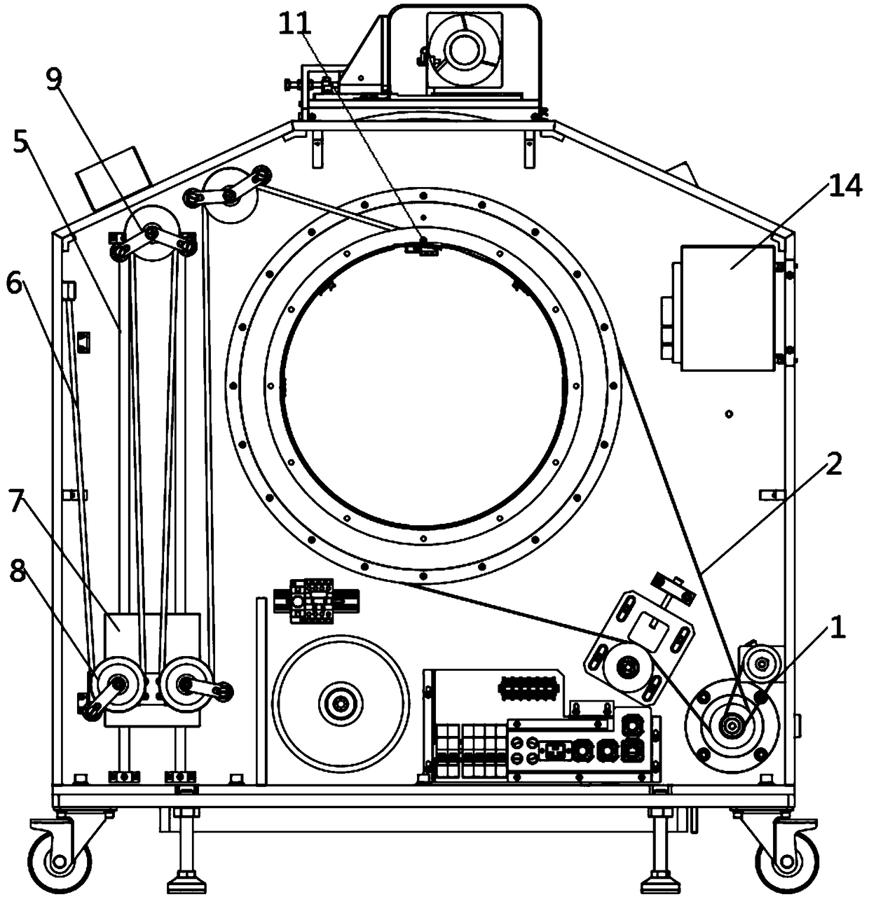
[0029] as attached Figure 1-3 As shown, it is a cable arrangement device for a mobile flat-panel CT of the present invention, which includes a rotating part and a cable arrangement part. The rotating part includes a motor 1, a first synchronous belt 2, and a rotating disk, and the rotating disk includes a synchronous pulley 3 and a drum. 4. The synchronous pulley 3 is installed on the frame, the drum 4 is installed on the synchronous pulley 3, and the motor 1 drives the synchronous pulley 3 to rotate through the first synchronous belt 2;

[0030] The cable section includes cable 6, cable static pulley 9, cable movable pulley 8, counterweight 7 and guide rail 5, guide rail 5 is fixed on the frame and is located on one side of the rotating disk, counterweight 7 is installed on the guide rail 5, and move up and down on the guide rail 5, the cable moving pulley 8 is installed...


PUM


Abstract

The invention relates to a wire arrangement device for moving cone beam CT. A synchronous belt wheel is arranged on a rack, a rotating cylinder is arranged on the synchronous belt wheel, a motor drives the synchronous belt wheel to rotate through a first synchronous belt, a guide rail is fixed to the rack, a balancing weight is arranged on the guide rail, a wire arrangement movable pulley is arranged on the balancing weight, a wire arrangement fixed pulley is located above the guide rail, a wire arrangement groove is formed in the rotating cylinder, a cable is fixed to the wire arrangement groove and then is arranged in an arranged wire in a penetrating manner, the arranged wire sequentially passes through the wire arrangement fixed pulley and the wire arrangement movable pulley and is fixed into a wire arrangement fixed buckle, when the CT machine works, the synchronous belt wheel drives the X light source and the rotating cylinder on the two sides of the rack to rotate by 360 degrees, the rotating cylinder drives the arranged wire, the arranged wire drives the balancing weight to move up and down on the guide rail through the wire arrangement fixed pulley and the wire arrangementmovable pulley, and therefore during spiral CT axial moving continuous rotating scanning, smooth traction and work of the wire arrangement cable and the synchronous wheel are safe and reliable, the wiring device is compact in structure, and the equipment size is effectively saved.

Description

technical field [0001] The invention belongs to the field of mobile CT, and in particular relates to a cable arrangement device for a mobile flat CT. Background technique [0002] Flat-panel CT is also called CBCT or Cone beam (cone beam) CT. As the name implies, it is a cone-beam projection computerized reconstruction tomography device. The principle is that the X-ray generator uses a low radiation dose (usually the tube current is about 10-20 mA) to make a circular DR (digital projection) around the projection body. According to). Then surround the projection body many times (360-720 times), and the data obtained in the "intersection" after digital projection are "recombined" in the computer to obtain a three-dimensional image. The projection principle of CBCT to obtain data is completely different from that of traditional sector scan CT. [0003] The biggest difference between CBCT and tomographic CT (helical CT) is that the projection data of tomographic CT is one-dim...

Claims


Application Information

Patent Timeline
IPC IPC(8): B65H59/10B65H59/18
CPCB65H59/10B65H59/18B65H2701/34
Inventor 张鲁兵张励
Owner 天津金曦医疗设备有限公司
Learn More