Tilt-shift tomography eye scanning system and method thereof

A scanning system and eye technology, used in eye testing equipment, diagnosis, medical science, etc., can solve the problem of inconvenient rotation, return, installation and maintenance, limited number of rotations of rotating devices, and difficulty in ensuring equipment safety, etc. problems, to achieve the effect of saving structural space, stable power supply, and improved safety

Active Publication Date: 2013-04-17
SHANGHAI MEDIWORKS PRECISION INSTR
View PDF6 Cites 0 Cited by
  • Summary
  • Abstract
  • Description
  • Claims
  • Application Information

AI Technical Summary

Problems solved by technology

[0003] 1. The power supply and the rotating device are connected by wired power supply. In this power supply method, the cable is often pulled by the rotation of the rotating part, which is easy to fatigue and break, which affects the service life of the instrument; the number of revolutions of the rotating device is limited.
[0004] 2. In order to prevent the cable from being damaged, the limit design is also complicated
[0005] 3. The safety of the equipment is difficult to guarantee after the limit is improper or the cable is damaged
[0006] 4. In addition, it must be reversed and reset before the next use
In this power supply method, the contacts are easily worn or oxidized, resulting in poor contact; due to assembly or mechanical failure, it is also easy to cause poor contact
[0008] As announced on September 15, 2010, the Chinese invention patent with the publication number CN 101828900 A provides "an axis-shifting tomography device", which basically realizes the rotating scanning function well, but uses a power supply cable for power supply, and its Claim 1 also clearly states "wired connection", so its rotation, return, installation and maintenance are bound to be inconvenient
[0009] At present, there is no axial shift tomographic eye scanning system and method that overcomes the above defects and has a simple structure, convenient assembly, reliable performance, and free rotation.

Method used


Image

  • Tilt-shift tomography eye scanning system and method thereof

Examples


Embodiment Construction

[0025] The specific embodiment of the present invention will be further elaborated below in conjunction with accompanying drawing:

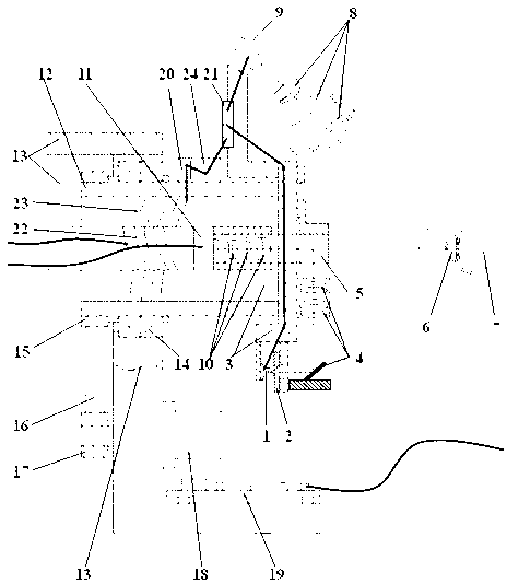
[0026] figure 1 Among them, the system includes a light source 1, a slit diaphragm 2, a rotating disk assembly 3, a projection lens group 4, a reflective device 5, an anterior tissue of the eye 6, an eye 7, an axis-shifting imaging lens 8, an axis-shifting camera 9, a focusing lens 10, a focusing Camera 11, rotating shaft 12, fixed bracket assembly 13, bearing 14, large pulley 15, belt 16, small pulley 17, motor 18, main circuit board 19, auxiliary circuit board 21; The plate 19 supplies power for the motor 18 to successively drive the small pulley 17, the belt 16, and the large pulley 15 to rotate, and then drive the rotating shaft 12 supported by the bearing 14 to rotate, and finally make it drive The rotating disc assembly 3 of the shifting imaging lens 8 and the shifting camera 9 rotates around the incident optical axis of the eye (7), a...


PUM


Abstract

The invention discloses a tilt-shift tomography eye scanning system and a method thereof, relates to the field of optical instruments for the ophthalmology, and aims at solving the problem of inconvenient rotation. The scanning system comprises a light source (1), a fracture diaphragm (2), a rotary disc assembly (3), a projecting mirror group (4), a reflective device (5), eye forepart tissues (6), an eye (7), tilt-shaft imaging lenses (8), tilt-shift cameras (9), focusing lenses (10), focusing cameras (11), a rotary shaft (12), a fixed support assembly (13), a bearing (14), a large belt wheel (15), a belt (16), a small belt wheel (17), a motor (18), a main circuit board (19), a power converter (20) and an auxiliary circuit board (21); a primary coil 922), a secondary coil (23) and an electrical storage device (24) are further arranged; and the rotation is convenient after power supply cables are omitted due to adoption of a wireless power supply or charge mode. The tilt-shift tomography eye scanning system and the method thereof are mainly used for shooting eye forepart tissues.

Description

technical field [0001] The invention relates to the field of ophthalmic optical instruments, in particular to an axis-shifting tomographic eye scanning system and a method thereof. Background technique [0002] At present, the following specific defects generally exist in the shift tomography eye scanning devices at home and abroad: [0003] 1. The power supply and the rotating device are connected by wired power supply. In this power supply method, the cable is often pulled by the rotating part, which is prone to fatigue and fracture, which affects the service life of the instrument; the number of revolutions of the rotating device is limited. [0004] 2. In order to prevent the cable from being damaged, the limit design is also complicated. [0005] 3. The safety of the equipment is difficult to guarantee when the limit is improper or the cable is damaged. [0006] 4. In addition, it must be reversed and reset before the next use. [0007] 5. Others use slip rings ...

Claims


Application Information

Patent Timeline
IPC IPC(8): A61B3/14
Inventor 王宏良魏悦陈文光孔昭松
Owner SHANGHAI MEDIWORKS PRECISION INSTR
Why Eureka
Try Eureka